 English
 Espaol
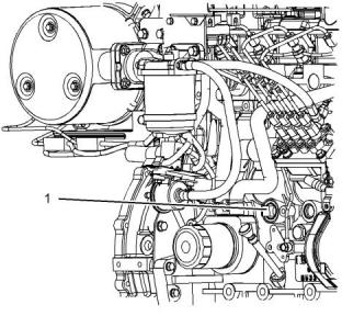
 Franais
 阿拉伯
阿拉伯 中文(簡)
中文(簡) Deutsch
 Italiano
 Português
 日本
日本 韓國
韓國 български
 hrvatski
 esky
esky Dansk
Dansk Nederlands
 suomi
suomi Ελληνικ
 印度
印度 norsk
norsk Polski
 Roman
Roman русский
 Svenska
 珀金斯403F-15T、404F-22、404F-22T柴油機維修操作保養,珀金斯403F-15T、404F-22、404F-22T柴油機維修操作保養技術支持中心,珀金斯403F-15T、404F-22、404F-22T柴油機維修操作保養代理商,珀金斯403F-15T、404F-22、404F-22T柴油機維修操作保養銷售服務中心,珀金斯403F-15T、404F-22、404F-22T柴油機維修操作保養價格規格資料查詢,寧波日昕動力科技有限公司

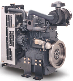
珀金斯403F-15T、404F-22、404F-22T柴油機維修操作保養二
詳細描述
Refill Capacities
Fluid Recommendations
Table 14
In order to maintain the correct balance between the
antifreeze and the additives, you must maintain the
recommended concentration of ELC. Lowering the
proportion of antifreeze lowers the proportion of
additive. This action will lower the ability of the
coolant to protect the system from pitting, from
cavitation, from erosion, and from deposits.
Coolant Service Life
Coolant Type
Service Life (1)
6,000 Service Hours or Three
Years
Perkins ELC
Commercial Heavy-Duty Anti-
freeze that meets ASTM
D6210
NOTICE
Do not use a conventional coolant to top-off a cooling
system that is filled with Extended Life Coolant (ELC).
3000 Service Hours or Two Years
A Perkins approved SCA
inhibitor
3000 Service Hours or Two Years
Do not use standard supplemental coolant additive
(SCA).
(1)
Use the interval that occurs first. The cooling system must also
be flushed out at this time.
When using Perkins ELC, do not use standard SCA's
or SCA filters.
ELC
Perkins provides ELC for use in the following
applications:
ELC Cooling System Cleaning
• Heavy-duty spark ignited gas engines
• Heavy-duty diesel engines
• Automotive applications
Note: If the cooling system is already using ELC,
cleaning agents are not required to be used at the
specified coolant change interval. Cleaning agents
are only required if the system has been
contaminated by the addition of some other type of
coolant or by cooling system damage.
The anti-corrosion package for ELC is different from
the anti-corrosion package for other coolants. ELC is
an ethylene glycol base coolant. However, ELC
contains organic corrosion inhibitors and antifoam
agents with low amounts of nitrite. Perkins ELC has
been formulated with the correct amount of these
additives in order to provide superior corrosion
protection for all metals in engine cooling systems.
Clean water is the only cleaning agent that is required
when ELC is drained from the cooling system.
Before the cooling system is filled, the heater control
(if equipped) must be set to the HOT position. Refer
to the OEM in order to set the heater control. After the
cooling system is drained and the cooling system is
refilled, operate the engine until the coolant level
reaches the normal operating temperature and until
the coolant level stabilizes. As needed, add the
coolant mixture in order to fill the system to the
specified level.
ELC is available in a premixed cooling solution with
distilled water. ELC is a 1:1 mixture. The Premixed
ELC provides freeze protection to −36 °C (−33 °F).
The Premixed ELC is recommended for the initial fill
of the cooling system. The Premixed ELC is also
recommended for topping off the cooling system.
Changing to Perkins ELC
Containers of several sizes are available. Consult
your Perkins distributor for the part numbers.
To change from heavy-duty antifreeze to the Perkins
ELC, perform the following steps:
ELC Cooling System Maintenance
NOTICE
Correct additions to the Extended Life
Coolant
Care must be taken to ensure that all fluids are con-
tained during performance of inspection, mainte-
nance, testing, adjusting and the repair of the
product. Be prepared to collect the fluid with suitable
containers before opening any compartment or disas-
sembling any component containing fluids.
NOTICE
Use only Perkins products for pre-mixed or concen-
trated coolants.
Dispose of all fluids according to local regulations and
mandates.
Mixing Extended Life Coolant with other products re-
duces the Extended Life Coolant service life. Failure
to follow the recommendations can reduce cooling
system components life unless appropriate corrective
action is performed.
1. Drain the coolant into a suitable container.
2. Dispose of the coolant according to local
regulations.
This document is printed from SPI². Not for RESALE
![]()
![]()
![]()
![]()
![]()
![]()
![]()
SEBU8609
61
Refill Capacities
Fluid Recommendations
3. Flush the system with clean water in order to
remove any debris.
• Drain the cooling system into a suitable container.
Dispose of the coolant according to local
regulations. Flush the system with clean water. Fill
the system with the Perkins ELC.
4. Use Perkins cleaner to clean the system. Follow
the instruction on the label.
• Drain a portion of the cooling system into a
suitable container according to local regulations.
Then, fill the cooling system with premixed ELC.
This procedure should lower the contamination to
less than 10 percent.
5. Drain the cleaner into a suitable container. Flush
the cooling system with clean water.
6. Fill the cooling system with clean water and
operate the engine until the engine is warmed to
49° to 66°C (120° to 150°F).
• Maintain the system as a conventional Heavy-Duty
Coolant. Treat the system with an SCA. Change
the coolant at the interval that is recommended for
the conventional Heavy-Duty Coolant.
NOTICE
Incorrect or incomplete flushing of the cooling system
can result in damage to copper and other metal
components.
Commercial Heavy-Duty Antifreeze and
SCA
To avoid damage to the cooling system, make sure to
completely flush the cooling system with clear water.
Continue to flush the system until all the signs of the
cleaning agent are gone.
NOTICE
Commercial Heavy-Duty Coolant which contains
as part of the corrosion protection system
Amine
must not be used.
7. Drain the cooling system into a suitable container
and flush the cooling system with clean water.
NOTICE
Never operate an engine without water temperature
regulators in the cooling system. Water temperature
regulators help to maintain the engine coolant at the
correct operating temperature. Cooling system prob-
Note: The cooling system cleaner must be thoroughly
flushed from the cooling system. Cooling system
cleaner that is left in the system will contaminate the
coolant. The cleaner may also corrode the cooling
system.
lems
can
develop
without
water
temperature
regulators.
8. Repeat Steps 6 and repeat steps 7 until the system
is completely clean.
Check the antifreeze (glycol concentration) in order to
ensure adequate protection against boiling or
freezing. Perkins recommends the use of a
refractometer for checking the glycol concentration. A
hydrometer should not be used.
9. Fill the cooling system with the Perkins Premixed
ELC.
ELC Cooling System Contamination
Perkins engine cooling systems should be tested at
500 hour intervals for the concentration of SCA.
NOTICE
Additions of SCA are based on the results of the test.
An SCA that is liquid may be needed at 500 hour
intervals.
Mixing ELC with other products reduces the effective-
ness of the ELC and shortens the ELC service life.
Use only Perkins Products for premixed or concen-
trate coolants. Failure to follow these recommenda-
Adding the SCA to Heavy-Duty Coolant at
the Initial Fill
tions
can result in shortened cooling system
component life.
Commercial heavy-duty antifreeze that meets ASTM
D4985 specifications MAY require an addition of SCA
at the initial fill. Read the label or the instructions that
are provided by the OEM of the product.
ELC cooling systems can withstand contamination to
a maximum of 10 percent of conventional heavy-duty
antifreeze or SCA. If the contamination exceeds 10
percent of the total system capacity, perform ONE of
the following procedures:
Use the equation that is in Table 15 to determine the
amount of Perkins SCA that is required when the
cooling system is initially filled.
This document is printed from SPI². Not for RESALE
![]()
![]()
![]()
![]()
![]()
![]()
![]()
![]()
![]()
62
SEBU8609
Refill Capacities
Fluid Recommendations
Table 15
Cleaning the System of Heavy-Duty
Antifreeze
Equation For Adding The SCATo The Heavy-Duty Coolant At
The Initial Fill
Perkins cooling system cleaners are designed to
clean the cooling system of harmful scale and
corrosion. Perkins cooling system cleaners dissolve
mineral scale, corrosion products, light oil
contamination, and sludge.
V × 0.045 = X
V is the total volume of the cooling system.
X is the amount of SCA that is required.
• Clean the cooling system after used coolant is
drained or before the cooling system is filled with
new coolant.
Table 16 is an example for using the equation that is
in Table 15 .
Table 16
Example Of The Equation For Adding The SCATo The Heavy-
Duty Coolant At The Initial Fill
• Clean the cooling system whenever the coolant is
contaminated or whenever the coolant is foaming.
Total Volume of the
Cooling System (V)
Multiplication
Factor
Amount of SCA
that is Required (X)
i04129134
15 L (4 US gal)
× 0.045
0.7 L (24 oz)
Fluid Recommendations
Adding The SCA to The Heavy-Duty
Coolant For Maintenance
General Lubricant Information
Because of government regulations regarding the
certification of exhaust emissions from the engine, the
lubricant recommendations must be followed.
Heavy-duty antifreeze of all types REQUIRE periodic
additions of an SCA.
Test the antifreeze periodically for the concentration
of SCA. For the interval, refer to the Operation and
Maintenance Manual, “Maintenance Interval
Schedule” (Maintenance Section). Test the
concentration of SCA.
• API
American Petroleum Institute
Society Of Automotive Engineers Inc.
Association des Constructers
• SAE
• ACEA
Additions of SCA are based on the results of the test.
The size of the cooling system determines the
amount of SCA that is needed.
European Automobiles .
• ECF-3
Engine Crankcase Fluid
Use the equation that is in Table 17 to determine the
amount of Perkins SCA that is required, if
necessary:
Licensing
Table 17
The Engine Oil Licensing and Certification System
by the American Petroleum Institute (API) and the
Association des Constructers European
Automobilesand (ACRA) is recognized by Perkins .
For detailed information about this system, see the
latest edition of the API publication No. 1509. Engine
oils that bear the API symbol are authorized by API.
Equation For Adding The SCATo The Heavy-Duty Coolant For
Maintenance
V × 0.014 = X
V is the total volume of the cooling system.
X is the amount of SCA that is required.
Table 18 is an example for using the equation that is
in Table 17 .
Table 18
Example Of The Equation For Adding The SCATo The Heavy-
Duty Coolant For Maintenance
Total Volume of the
Cooling System (V)
Multiplication
Factor
Amount of SCA
that is Required (X)
15 L (4 US gal)
× 0.014
0.2 L (7 oz)
This document is printed from SPI². Not for RESALE


![]()
![]()
![]()
![]()
![]()
SEBU8609
63
Refill Capacities
Fluid Recommendations
The chemical limits were developed in order to
maintain the expected life of the engine
aftertreatment system. The performance of the
engine aftertreatment system can be adversely
affected if oil that is not specified in table 19 is used.
The life of your Aftertreatmentsystem is defined by
the accumulation of ash on the surface of the filter.
Ash is the inert part of the particulate matter. The
system is designed in order to collect this particulate
matter. There is a very small percentage of particulate
matter that is left behind as the soot is burnt. This
matter will eventually block the filter, causing loss of
performance and increased fuel consumption. Most
of the ash comes from the engine oil which is
gradually consumed during normal operation. This
ash is passes through the exhaust. To meet the
designed life of the product, the use of the
appropriate engine oil is essential. The oil
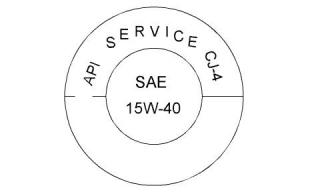
Illustration 39
g01987816
Typical API symbol
specification that is listed in table 19 has low ash
content.
Terminology
Maintenance intervals for engines that use
biodiesel – The oil change interval can be adversely
affected by the use of biodiesel. Use oil analysis in
order to monitor the condition of the engine oil. Use
oil analysis also in order to determine the oil change
interval that is optimum.
Certain abbreviations follow the nomenclature of SAE
J754. Some classifications follow SAE J183
abbreviations, and some classifications follow the
EMA Recommended Guideline on Diesel Engine Oil.
In addition to Perkins definitions, there are other
definitions that will be of assistance in purchasing
lubricants. Recommended oil viscosities can be
found in this publication, “Fluid Recommendations/
Engine Oil” topic (Maintenance Section).
Note: These engine oils are not approved by
Perkins and these engine oils must not be used:
CC, CD, CD-2, CF-4, CG-4, CH-4 and CI-4.
Engine Oil
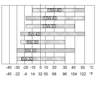
Lubricant Viscosity Recommendations
for Direct Injection (DI) Diesel Engines
Commercial Oils
NOTICE
The correct SAE viscosity grade of oil is determined
by the minimum ambient temperature during cold
engine start-up, and the maximum ambient
temperature during engine operation.
Perkins require the use of the following specifica-
tion of engine oil. Failure to use the appropriate
specification of engine oil will reduce the life of
your engine. Failure to use the appropriate speci-
fication of engine oil will also reduce the life of
your aftertreatment system.
Refer to illustration40 (minimum temperature) in
order to determine the required oil viscosity for
starting a cold engine.
Table 19
Refer to illustration 40 (maximum temperature) in
order to select the oil viscosity for engine operation at
the highest ambient temperature that is anticipated.
Classifications for the 400F IndustrialEngines
Oil Specification
Generally, use the highest oil viscosity that is
available to meet the requirement for the temperature
at start-up.
CJ-4
ACEA E9
ECF-3
API CJ-4 and ACEA E9 oil categories have the
following chemical limits:
• 0.1 percent maximum sulfated ash
• 0.12 percent maximum phosphorous
• 0. 4 percent maximum sulfur
This document is printed from SPI². Not for RESALE
![]()
![]()
![]()
![]()
![]()
64
SEBU8609
Refill Capacities
Fluid Recommendations
• See the appropriate “Lubricant Viscosities”. Refer
to the illustration 40 in order to find the correct oil
viscosity grade for your engine.
• At the specified interval, service the engine. Use
new oil and install a new oil filter.
• Perform maintenance at the intervals that are
specified in the Operation and Maintenance
Manual, “Maintenance Interval Schedule”.
Oil analysis
Some engines may be equipped with an oil sampling
valve. If oil analysis is required, the oil sampling valve
is used to obtain samples of the engine oil. The oil
analysis will complement the preventive maintenance
program.
The oil analysis is a diagnostic tool that is used to
determine oil performance and component wear
rates. Contamination can be identified and measured
by using oil analysis. The oil analysis includes the
following tests:
Illustration 40
g02932046
Lubricant Viscosities
• The Wear Rate Analysis monitors the wear of the
engines metals. The amount of wear metal and
type of wear metal that is in the oil is analyzed. The
increase in the rate of engine wear metal in the oil
is as important as the quantity of engine wear
metal in the oil.
Supplemental heat is recommended for cold soaked
starts below the minimum ambient temperature.
Supplemental heat may be required for cold soaked
starts that are above the minimum temperature that is
stated, depending on the parasitic load and other
factors. Cold soaked starts occur when the engine
has not been operated for a period of time. This
interval will allow the oil to become more viscous due
to cooler ambient temperatures.
• Tests are conducted in order to detect
contamination of the oil by water, glycol, or fuel.
Aftermarket Oil Additives
• The Oil Condition Analysis determines the loss of
the oils lubricating properties. An infrared analysis
is used to compare the properties of new oil to the
properties of the used oil sample. This analysis
allows technicians to determine the amount of
deterioration of the oil during use. This analysis
also allows technicians to verify the performance
of the oil according to the specification during the
entire oil change interval.
Perkins does not recommend the use of aftermarket
additives in oil. It is not necessary to use aftermarket
additives in order to achieve the engines maximum
service life or rated performance. Fully formulated,
finished oils consist of base oils and of commercial
additive packages. These additive packages are
blended into the base oils at precise percentages in
order to help provide finished oils with performance
characteristics that meet industry standards.
There are no industry standard tests that evaluate the
performance or the compatibility of aftermarket
additives in finished oil. Aftermarket additives may not
be compatible with the finished oils additive package,
which could lower the performance of the finished oil.
The aftermarket additive could fail to mix with the
finished oil. This failure could produce sludge in the
crankcase. Perkins discourages the use of
aftermarket additives in finished oils.
To achieve the best performance from a Perkins
engine, conform to the following guidelines:
This document is printed from SPI². Not for RESALE
![]()
![]()
![]()
SEBU8609
65
Refill Capacities
Fluid Recommendations
i04057529
Satisfactory engine performance is dependent on the
use of a good quality fuel. The use of a good quality
fuel will give the following results: long engine life and
acceptable exhaust emissions levels . The fuel must
meet the minimum requirements that are stated in the
table 20 .
Fluid Recommendations
• Glossary
NOTICE
• ISO International Standards Organization
The footnotes are of the key part Perkins Specifica-
tion for Distillate Diesel Fuel Table. Read ALL of the
footnotes.
• ASTMAmerican Society for Testing and Materials
• HFRRHigh Frequency Reciprocating Rig for
Lubricity testing of diesel fuels
• FAMEFatty Acid Methyl Esters
• CFRCo-ordinating Fuel Research
• ULSDUltra Low Sulfur Diesel
• RMERape Methyl Ester
• SMESoy Methyl Ester
• EPA Environmental Protection Agency of the
United States
• PPM Parts Per Million
• DPF Diesel Particulate Filter
General Information
NOTICE
Every attempt is made to provide accurate, up-to-date
information. By use of this document you agree that
Perkins Engines Company Limited is not responsible
for errors or omissions.
NOTICE
These recommendations are subject to change with-
out notice. Contact your local Perkins distributor for
the most up-to-date recommendations.
The fuel information within this OMM is for use with
the following engine models: 403F-15T, 404F-22,
404F-22T, and 404F-22TA
Diesel Fuel Requirements
Perkins is not in a position to continuously evaluate
and monitor all worldwide distillate diesel fuel
specifications that are published by governments and
technological societies.
The Perkins table for Specification for Distillate
Diesel Fuel provides a known reliable baseline in
order to judge the expected performance of distillate
diesel fuels that are derived from conventional
sources.
This document is printed from SPI². Not for RESALE
![]()
![]()
![]()
![]()
![]()
![]()
![]()
66
SEBU8609
Refill Capacities
Fluid Recommendations
Table 20
Perkins Specification for DistillateDiesel Fuel(1)
Property
UNITS
Requirements
ASTMTest
ISOTest
Aromatics
Ash
%Volume
%Weight
35% maximum
D1319
D482
ISO3837
ISO6245
0.01% maximum
Carbon Residue on 10%
Bottoms
%Weight
0.35% maximum
D524
ISO4262
Cetane Number (2)
Cloud Point
-
40 minimum
D613/D6890
ISO5165
ISO3015
°C
The cloud point must not ex- D2500
ceed the lowest expected
ambient temperature.
Copper Strip Corrosion
-
No. 3 maximum
D130
ISO2160
Density at 15 °C (59 °F)(3) Kg / M
3
801 minimum and 876
maximum
No equivalent test
ISO 3675ISO 12185
ISO3405
Distillation
°C
10% at 282 °C (539.6 °F)
maximum
D86
90% at 360 °C (680 °F)
maximum
Flash Point
°C
-
legal limit
D93
ISO2719
Thermal Stability
Minimum of 80% reflectance D6468
after aging for 180 minutes
at 150 °C (302 °F)
No equivalent test
Pour Point
°C
6 °C (42.8 °F) minimum be- D97
low ambient temperature
ISO3016
Sulfur (1)
%mass
0.0015
D5453/D26222
ISO 20846ISO 20884
ISO3405
Kinematic Viscosity (4)
2
“MM” “/S (cSt)”
The viscosity of the fuel that D445
is delivered to the fuel injec-
tion pump. “1.4 minimum/
4.5 maximum”
Water and sediment
Water
% weight
% weight
% weight
mg/100mL
0.1% maximum
0.1% maximum
0.05% maximum
D1796
D1744
D473
ISO3734
No equivalent test
ISO3735
Sediment
Gums and Resins (5)
10 mg per 100 mL
maximum
D381
ISO6246
Lubricity corrected wear
mm
0.52 maximum
D6079
ISO12156-1
scar diameter at 60 °C
(140 °F). (6)
(1)
This specification includes the requirements for Ultra Low Sulfur Diesel (ULSD). ULSD fuel will have ≤ 15 ppm (0.0015%) sulfur. Refer to
ASTM D5453, ASTM D2622, or ISO 20846, ISO 20884 test methods.
(2)
(3)
A fuel with a higher cetane number is recommended in order to operate at a higher altitude or in cold weather.
“Via standards tables, the equivalent API gravity for the minimum density of 801 kg / m (kilograms per cubic meter) is 45 and for the maximum
3
density of 876 kg / m is 30”.
3
(4)
The values of the fuel viscosity are the values as the fuel is delivered to the fuel injection pumps. Fuel should also meet the minimum viscosity
requirementand the fuel should meet the maximum viscosity requirements at 40 °C (104 °F) of either the ASTM D445 test method or the ISO
3104 test method. If a fuel with a low viscosity is used, cooling of the fuel may be required to maintain “1.4 cSt”or greater viscosity at the fuel in-
jection pump. Fuels with a high viscosity might require fuel heaters in order to lower the viscosity to “1.4 cSt” at the fuel injection pump.
Follow the test conditions and procedures for gasoline (motor).
The lubricity of a fuel is a concern with ultra low sulfur fuel. To determine the lubricity of the fuel, use the ISO 12156-1 or ASTM D6079 High
Frequency Reciprocating Rig (HFRR) test. If the lubricity of a fuel does not meet the minimum requirements, consult your fuel supplier. Do not
treat the fuel without consulting the fuel supplier. Some additives are not compatible. These additives can cause problems in the fuel system.
(5)
(6)
This document is printed from SPI². Not for RESALE
![]()
SEBU8609
67
Refill Capacities
Fluid Recommendations
Engines that are manufactured by Perkins are
certified with the fuel that is prescribed by the United
States Environmental Protection Agency. Engines
that are manufactured by Perkins are certified with
the fuel that is prescribed by the European
Certification. Perkins does not certify diesel engines
on any other fuel.
Note: The owner and the operator of the engine has
the responsibility of using the fuel that is prescribed
by the EPA and other appropriate regulatory
agencies.
NOTICE
Operating with fuels that do not meet the Perkins rec-
ommendations can cause the following effects: Start-
ing difficulty, poor combustion, deposits in the fuel
injectors, reduced service life of the fuel system, de-
posits in the combustion chamber and reduced serv-
ice life of the engine.
The Perkins 400F diesel engines must be operated
using Ultra Low Sulfur Diesel. The sulphur content of
this fuel must be lower than 15 PPM. This fuel
complies with the emissions regulations that are
prescribed by the Environmental Protection Agency
of the United States
The fuels that are listed in the table 21 are
acceptable to use on all 400F engines.
Table 21
Acceptable Fuel Specification for the 400F Engines(1)
Fuel Specification
EN590
Comments
European Automotive Diesel Fuel (DERV)
ASDM D975 GRADE 1D S15
“North American Light Distillate Diesel fuel with less than 15 PPM sulfur
level”
ASTM D975 GRADE 2D S15
JIS K2204
“North American Middle Distillate general purpose Diesel fuel with less
than 15 PPM sulfur level”
“Japanese Diesel Fuel” Must meet the requirements that are stated in
the section “Lubricity”.
BS 2869 or equivalent
“EU Off Road Diesel fuel. Acceptable from 2011 MUST have less than
10 PPM sulfur level”
(1)
All the fuels must comply with the specification in the table for the Perkins Specification DistillateDiesel Fuel .
Diesel Fuel Characteristics
Cetane numbers in excess of 45 are normally
expected from current diesel fuel. However, a cetane
number of 40 may be experienced in some territories.
The United States of America is one of the territories
that can have a low cetane value. A minimum cetane
value of 40 is required during average starting
conditions. A fuel with higher cetane number is
recommended for operations at high altitudes or in
cold-weather operations.
Cetane Number
Fuel that has a high cetane number will give a shorter
ignition delay. A high cetane number will produce a
better ignition quality. Cetane numbers are derived for
fuels against proportions of cetane and
heptamethylnonane in the standard CFR engine.
Refer to ISO 5165 for the test method.
Fuel with a low cetane number can be the root cause
of problems during a cold start.
This document is printed from SPI². Not for RESALE
![]()
![]()
![]()
68
SEBU8609
Refill Capacities
Fluid Recommendations
Viscosity
By using the test methods ASTM D5453, ASTM
D2622, or ISO 20846 ISO 20884, the content of sulfur
in ultra low sulfur (ULSD) fuel must be below 15 PPM
0.0015%. The lubricity of these fuels must not exceed
wear scar diameter of 0.52 mm (0.0205 inch). The
fuel lubricity test must be performed on an HFRR,
operated at 60 °C (140 °F). Refer to ISO 12156-1.
Viscosity is the property of a liquid of offering
resistance to shear or flow. Viscosity decreases with
increasing temperature. This decrease in viscosity
follows a logarithmic relationship for normal fossil
fuel. The common reference is to kinematic viscosity.
kinematic viscosity is the quotient of the dynamic
viscosity that is divided by the density. The
determination of kinematic viscosity is normally by
readings from gravity flow viscometers at standard
temperatures. Refer to ISO 3104 for the test method.
Lubricity
Lubricity is the capability of the fuel to prevent pump
wear. The fluids lubricity describes the ability of the
fluid to reduce the friction between surfaces that are
under load. This ability reduces the damage that is
caused by friction. Fuel injection systems rely on the
lubricating properties of the fuel. Until fuel sulfur limits
were mandated, the fuels lubricity was generally
believed to be a function of fuel viscosity.
The viscosity of the fuel is significant because fuel
serves as a lubricant for the fuel system components.
Fuel must have sufficient viscosity in order to
lubricate the fuel system in both extremely cold
temperatures and extremely hot temperatures . If the
kinematic viscosity of the fuel is lower than “1.4 cSt”
at the fuel injection pump, damage to the fuel injection
pump can occur. This damage can be excessive
scuffing and seizure. Low viscosity may lead to
difficult hot restarting, stalling, and loss of
The lubricity has particular significance to the current
low viscosity fuel , low sulfur fuel, and low aromatic
fossil fuel. These fuels are made in order to meet
stringent exhaust emissions. A test method for
measuring the lubricity of diesel fuels has been
developed and the test is based on the HFRR method
that is operated at 60°C (140°F). Refer to ISO 12156
part 1 and CEC document F06-A-96 for the test
method.
performance. High viscosity may result in seizure of
the pump.
Perkins recommends kinematic viscosities of 1.4 and
4.5 mm2/sec that is delivered to the fuel injection
pump. If a fuel with a low viscosity is used, cooling of
the fuel may be required to maintain 1.4 cSt or
greater viscosity at the fuel injection pump. Fuels with
a high viscosity might require fuel heaters in order to
lower the viscosity to 4.5 cSt at the fuel injection
pump.
Lubricity wear scar diameter of 0.52 mm
(0.0205 inch) MUST NOT be exceeded. The fuel
lubricity test must be performed on an HFRR,
operated at 60 °C (140 °F). Refer to ISO 12156-1.
Distillation
Density
Distillation is an indication of the mixture of different
hydrocarbons in the fuel. A high ratio of light weight
hydrocarbons can affect the characteristics of
combustion.
Density is the mass of the fuel per unit volume at a
specific temperature. This parameter has a direct
influence on engine performance and a direct
influence on emissions. This influence determines
from a heat output given injected volume of fuel. This
parameter is quoted in the following kg/m at 15 °C
(59 °F).
Recommendation for Biodiesel
Biodiesel is a fuel that can be defined as mono-alkyl
esters of fatty acids . Biodiesel is a fuel that can be
made from various feedstock. The most commonly
available biodiesel in Europe is Rape Methyl Ester
(REM) . This biodiesel is derived from rapeseed oil .
Soy Methyl Ester (SME) is the most common
biodiesel in the United States. This biodiesel is
derived from soybean oil . Soybean oil or rapeseed
oil are the primary feedstocks. These fuels are
together known as Fatty Acid Methyl Esters (FAME) .
Perkins recommends a value of density of 841 kg/m
in order to obtain the correct power output. Lighter
fuels are acceptable but these fuels will not produce
the rated power.
Sulfur
The level of sulfur is governed by emissions
legislations . Regional regulation, national
regulations, or international regulations can require a
fuel with a specific sulfur limit. The sulfur content of
the fuel and the fuel quality must comply with all
existing local regulations for emissions.
This document is printed from SPI². Not for RESALE
![]()
SEBU8609
69
Refill Capacities
Fluid Recommendations
Raw pressed vegetable oils are NOTacceptable for
use as a fuel in any concentration in compression
engines . Without esterification, these oils solidify in
the crankcase and the fuel tank. These fuels may not
be compatible with many of the elastomers that are
used in engines that are manufactured today. In
original forms, these oils are not suitable for use as a
fuel in compression engines . Alternate base stocks
for biodiesel may include animal tallow, waste
cooking oils , or various other feedstocks. In order to
use any of the products that are listed as fuel, the oil
must be esterified .
Perkins recognizes the fact that additives may be
required in some special circumstances. Contact your
fuel supplier for those circumstances when fuel
additives are required. Your fuel supplier can
recommend the appropriate fuel additive and the
correct level of treatment.
Note: For the best results, your fuel supplier should
treat the fuel when additives are required. The treated
fuel must meet the requirements that are stated in
table 20 .
Perkins Diesel Fuel System Cleaner
Fuel made of 100 percent FAME is generally referred
to as B100 biodiesel or neat biodiesel.
Perkins T400012 Fuel Cleaner is the only fuel
Biodiesel can be blended with distillate diesel fuel.
The blends can be used as fuel. The most commonly
available biodiesel blends are B7, which is 7 percent
biodiesel and 95 percent distillate diesel fuel.
cleaner that is recommended by Perkins .
If biodiesel or biodiesel blends of fuel are to be used,
Perkins require the use of Perkins fuel cleaner. The
use of the fuel is in order to remove deposits within
the fuel system that is created with the use of
biodiesel. For more information on the use of
biodiesel and biodiesel blends refer to
Note: The percentages given are volume-based.
The U.S. distillate diesel fuel specification ASTM
D975-09a includes up to B5 (5 percent) biodiesel.
“Recommendation for Biodiesel”.
European distillate diesel fuel specification EN590
includes up B7 (7 percent) biodiesel. Any diesel fuel
in Europe may contain up to B5 or in some regions up
to B7 biodiesel fuel.
Perkins fuel cleaner will remove deposits that can
form in the fuel system with the use of biodiesel and
biodiesel blends. These deposits can create a loss of
power and engine performance.
Once the fuel cleaner has been added to the fuel, the
deposits within the fuel system are removed after 30
hours of engine operation. For maximum results,
continue to use the fuel cleaner for up to 80 hours.
Perkins fuel cleaner can be used on an on-going
basis with no adverse impact on engine or fuel
system durability.
Note: Engines that are manufactured by Perkins are
certified by use of the prescribed Environmental
Protection Agency (EPA) and European Certification
fuels. Perkins does not certify engines on any other
fuel. The user of the engine has the responsibility of
using the correct fuel that is recommended by the
manufacturer and allowed by the EPA and other
appropriate regulatory agencies.
Details instruction on the rate of which the fuel
cleaner must be use are on the container.
Fuel for Cold Weather Operation
Note: Perkins fuel cleaner is compatible with
existing and U.S. EPATier 4 nonroad certified diesel
engine emission control catalysts and particulate
filters. Perkins fuel system cleaner contains less
than 15 ppm of sulfur and is acceptable for use with
ULSD fuel.
The European standard EN590 contains climate
dependant requirements and a range of options. The
options can be applied differently in each country.
There are five classes that are given to arctic climates
and severe winter climates . 0, 1, 2, 3 and 4.
Fuel that complies with EN590 CLASS 4 can be used
at temperatures as low as −44 °C (−47.2 °F). Refer
to EN590 for a detailed discretion of the physical
properties of the fuel.
The diesel fuel ASTM D975 1-D used in the United
States of America may be used in very cold
temperatures that are below −18 °C (−0.4 °F).
Aftermarket Fuel Additives
Supplemental diesel fuel additives are not generally
recommended . This recommendation is due to
potential damage to the fuel system or the engine.
Your fuel supplier or the fuel manufacturer will add the
appropriate supplemental diesel fuel additives.
This document is printed from SPI². Not for RESALE
![]()
70
SEBU8609
Maintenance Recommendations
System Pressure Release
Maintenance
Recommendations
Components for the driven equipment should also be
considered. When possible, remove the component
that requires welding. When welding on an engine
that is equipped with an ECM and removal of the
component is not possible, the following procedure
must be followed. This procedure minimizes the risk
to the electronic components.
i04056177
System Pressure Release
1. Stop the engine. Remove the electrical power from
the ECM.
Coolant System
2. Ensure that the fuel supply to the engine is turned
off.
3. Disconnect the negative battery cable from the
battery. If a battery disconnect switch is installed,
open the switch.
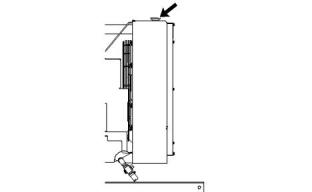
Pressurized system: Hot coolant can cause seri-
ous burn. To open cap, stop engine, wait until ra-
diator is cool. Then loosen cap slowly to relieve
the pressure.
4. Disconnect all electronic components from the
wiring harnesses. Include the following
components:
Ensure that the power supply is isolated before any
service or repair is performed.
• Electronic components for the driven equipment
To relieve the pressure from the coolant system, turn
off the engine. Allow the cooling system pressure cap
to cool. Remove the cooling system pressure cap
slowly in order to relieve pressure.
• ECM
• Sensors
• Electronically controlled valves
• Relays
Fuel System
To relieve the pressure from the fuel system, turn off
the engine.
• Aftertreatment ID module
Engine Oil
NOTICE
To relieve pressure from the lubricating system, turn
off the engine.
Do not use electrical components (ECM or ECM sen-
sors) or electronic component grounding points for
grounding the welder.
i04055929
Welding on Engines with
Electronic Controls
Correct welding procedures are necessary in order to
avoid damage to the following components:
• Electronic Control Module (ECM) on the engine
• Clean Emissions Module (CEM)
• Sensors
• Associated components
This document is printed from SPI². Not for RESALE
![]()
![]()
![]()
![]()
![]()
SEBU8609
71
Maintenance Recommendations
Severe Service Application
i04150276
Severe Service Application
Severe service is the application of an engine that
exceeds the current published standards for that
engine. Perkins maintains standards for the
following engine parameters:
• Performance such as power range, speed range,
and fuel consumption
• Fuel quality
• Operational Altitude
• Maintenance intervals
• Oil selection and maintenance
• Coolant type and maintenance
• Environmental qualities
• Installation
• The temperature of the fluid in the engine
Refer to the standards for the engine or consult your
Perkins &a, mp;n, bsp;dealer or your Perkins distributor in order to
determine if the engine is operating within the defined
parameters.
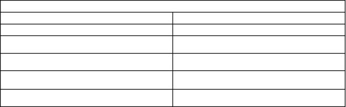
Illustration 41
g01075639
Use the example above. The current flow from the
welder to the ground clamp of the welder will not
damage any associated components.
Severe service operation can accelerate component
wear. Engines that operate under severe conditions
may need more frequent maintenance intervals in
order to ensure maximum reliability and retention of
full service life.
(1) Engine
(2) Welding electrode
(3) Keyswitch in the OFF position
(4) Battery disconnect switch in the open position
(5) Disconnected battery cables
(6) Battery
(7) Electrical/Electronic component
(8) Minimum distance between the component that is being welded
and any electrical/electronic component
(9) The component that is being welded
(10) Current path of the welder
(11) Ground clamp for the welder
Due to individual applications, it is not possible to
identify all of the factors which can contribute to
severe service operation. Consult your Perkins
dealer or your Perkins distributor for the unique
maintenance that is necessary for the engine.
The operating environment, incorrect operating
procedures, and incorrect maintenance procedures
can be factors which contribute to a severe service
application.
5. When possible, connect the ground clamp for the
welding equipment directly to the engine
component that will be welded. Place the clamp as
close as possible to the weld. Close positioning
reduces the risk of welding current damage to the
engine bearings, to the electrical components, and
to other components.
EnvironmentalFactors
Ambient temperatures – The engine may be
exposed to extended operation in cold environments
or hot environments. Valve components can be
damaged by carbon buildup if the engine is frequently
started and stopped in cold temperatures. Hot intake
air reduces engine performance.
6. Protect the wiring harnesses from welding debris
and/or from welding spatter.
7. Use standard welding procedures to weld the
materials together.
Quality of the air – The engine may be exposed to
extended operation in an environment that is dirty or
dusty, unless the equipment is cleaned regularly.
Mud, dirt, and dust can encase components.
Maintenance can be difficult. The buildup can contain
corrosive chemicals.
This document is printed from SPI². Not for RESALE
![]()
![]()
![]()
72
SEBU8609
Maintenance Recommendations
Severe Service Application
Buildup – Compounds, elements, corrosive
chemicals, and salt can damage some components.
Altitude – Problems can arise when the engine is
operated at altitudes that are higher than the intended
settings for that application. Necessary adjustments
should be made.
Incorrect Operating Procedures
• Extended operation at low idle
• Frequent hot shutdowns
• Operating at excessive loads
• Operating at excessive speeds
• Operating outside the intended application
Incorrect Maintenance Procedures
• Extending the maintenance intervals
• Failure to use recommended fuel, lubricants, and
coolant/antifreeze
This document is printed from SPI². Not for RESALE
![]()
SEBU8609
73
Maintenance Recommendations
Maintenance Interval Schedule
i05146189
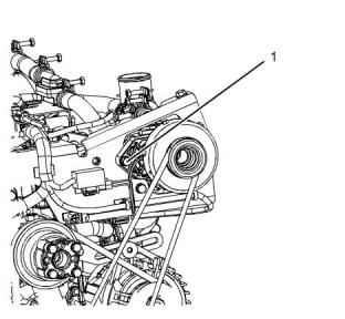
“Belts - Inspect/Replace”.........................................77
“Crankcase Breather (Canister) - Replace”.............83
“Engine Valve Lash - Check”...................................89
“Turbocharger - Inspect”..........................................96
MaintenanceInterval Schedule
When Required
Every 2000 Service Hours
“Battery - Replace”...................................................75
“Battery or Battery Cable - Disconnect”...................76
“Engine - Clean”.......................................................85
“Fuel System - Prime”..............................................92
“Alternator - Inspect”................................................73
“Engine Mounts - Inspect” .......................................86
“Starting Motor - Inspect”.........................................96
Every 3000 Service Hours
Daily
“Coolant Temperature Regulator - Replace” ...........82
“Diesel Particulate Filter - Clean”.............................84
“Fuel Injector - Test/Change”...................................91
“Glow Plugs (ARD Combustion) - Replace”............93
“Radiator Pressure Cap - Clean/Replace”...............96
“Water Pump - Inspect”............................................98
“Coolant Level - Check”...........................................80
“Engine Air Cleaner Service Indicator - Inspect”.....85
“Engine Air Precleaner - Check/Clean”...................86
“Engine Oil Level - Check”.......................................86
“Walk-Around Inspection”........................................97
Every 50 Service Hours or Weekly
Every 3000 Service Hours or 2
Years
“Fuel Tank Water and Sediment - Drain”.................93
Every 250 Service Hours or 6
Months
“Coolant (Commercial Heavy-Duty) - Change” .......77
Every 12 000 Service Hours or 6
Years
“Alternator and Fan Belts - Inspect/Adjust” .............74
“Belts - Inspect/Adjust/Replace”..............................76
“Coolant (ELC) - Change”........................................79
Every 500 Service Hours
Commissioning
“Engine Air Cleaner Element - Replace” .................85
“Fan Clearance - Check” .........................................90
“Fuel Filter (In-Line) - Replace”................................90
“Fuel System Secondary Filter - Replace” ..............92
“Fan Clearance - Check” .........................................90
i02322311
Alternator - Inspect
Every 500 Service Hours or 1 Year
Perkins recommends a scheduled inspection of the
alternator. Inspect the alternator for loose
connections and correct battery charging. Check the
ammeter (if equipped) during engine operation in
order to ensure correct battery performance and/or
correct performance of the electrical system. Make
repairs, as required.
“Battery Electrolyte Level - Check”..........................75
“Cooling System Supplemental Coolant Additive
(SCA) - Test/Add”.....................................................82
“Engine Oil and Filter - Change”..............................87
“Hoses and Clamps - Inspect/Replace”...................94
“Radiator - Clean” ....................................................95
Every 1000 Service Hours
“Alternator and Fan Belts - Replace”.......................75
This document is printed from SPI². Not for RESALE
![]()
74
SEBU8609
Maintenance Recommendations
Alternator and Fan Belts - Inspect/Adjust
Check the alternator and the battery charger for
correct operation. If the batteries are correctly
charged, the ammeter reading should be very near
zero. All batteries should be kept charged. The
batteries should be kept warm because temperature
affects the cranking power. If the battery is too cold,
the battery will not crank the engine. When the engine
is not run for long periods of time or if the engine is
run for short periods, the batteries may not fully
charge. A battery with a low charge will freeze more
easily than a battery with a full charge.
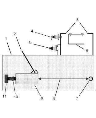
Install the gauge (1) at the center of the belt between
the alternator and the crankshaft pulley and check the
belt tension. The correct tension for a new belt is
400 N (90 lb) to 489 N (110 lb). The correct tension
for a used belt that has been in operation for 30
minutes or more at the rated speed is 267 N (60 lb) to
356 N (80 lb).
Adjustment
i05162309
Alternator and Fan Belts -
Inspect/Adjust
Inspection
To maximize the engine performance, inspect the belt
for wear and for cracking. Replace a belt that is worn
or damaged.
If a belt is too loose, vibration causes unnecessary
wear on the belt and pulleys. Loose belts may slip
enough to cause overheating.
To accurately check the belt tension, a suitable gauge
should be used.
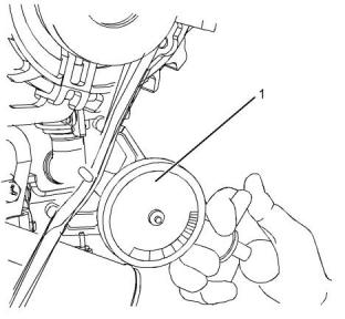
Illustration 43
g03316634
1. Loosen bolts (1) and adjusting bolt (2). Loosen bolt
(4).
2. Move the alternator (3) in order to increase or
decrease the belt tension.
3. Tighten adjusting bolt (2). Tighten bolts (1) and
tighten bolt (4). Refer to the Specifications Manual
for the correct torque settings.
Illustration 42
g03316638
Typical example
(1) Burroughs Gauge
This document is printed from SPI². Not for RESALE
![]()
![]()
![]()

![]()
![]()
SEBU8609
75
Maintenance Recommendations
Alternator and Fan Belts - Replace
i05162326
Alternator and Fan Belts -
Replace
The battery cables or the batteries should not be
removed with the battery cover in place. The bat-
tery cover should be removed before any servic-
ing is attempted.
Removing the battery cables or the batteries with
the cover in place may cause a battery explosion
resulting in personal injury.
1. Switch the engine to the OFF position. Remove all
electrical loads.
2. Turn off any battery chargers. Disconnect any
battery chargers.
3. The NEGATIVE “-” cable connects the NEGATIVE
“-” battery terminal to the NEGATIVE “-” terminal
on the starting motor. Disconnect the cable from
the NEGATIVE “-” battery terminal.
4. The POSITIVE “+” cable connects the POSITIVE
“+” battery terminal to the POSITIVE “+” terminal
on the starting motor. Disconnect the cable from
the POSITIVE “+” battery terminal.
Note: Always recycle a battery. Never discard a
battery. Dispose of used batteries to an appropriate
recycling facility.
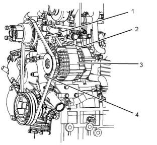
Illustration 44
g03316634
(1) Securing bolt
(2) Adjusting bolt
(3) Alternator
5. Remove the used battery.
(4) Lower securing bolt
6. Install the new battery.
The air pump belt must be removed before the fan
belt can be removed.
Note: Before the cables are connected, ensure that
the engine start switch is OFF.
7. Connect the cable from the starting motor to the
POSITIVE “+” battery terminal.
Refer to the Disassembly and Assembly Manual for
the installation procedure and the removal procedure
for both belts.
i02322315
8. Connect the NEGATIVE “-” cable to the
NEGATIVE “-” battery terminal.
Battery - Replace
i02747977
Battery Electrolyte Level -
Check
Batteries give off combustible gases which can
explode. A spark can cause the combustible
gases to ignite. This can result in severe personal
injury or death.
When the engine is not run for long periods of time or
when the engine is run for short periods, the batteries
may not fully recharge. Ensure a full charge in order
to help prevent the battery from freezing. If batteries
are correctly charged, the ammeter reading should be
very near zero, when the engine is in operation.
Ensure proper ventilation for batteries that are in
an enclosure. Follow the proper procedures in or-
der to help prevent electrical arcs and/or sparks
near batteries. Do not smoke when batteries are
serviced.
This document is printed from SPI². Not for RESALE
![]()
![]()
![]()
![]()
![]()
![]()
![]()
76
SEBU8609
Maintenance Recommendations
Battery or Battery Cable - Disconnect
4. Clean all disconnected connection and battery
terminals.
All lead-acid batteries contain sulfuric acid which
can burn the skin and clothing. Always wear a
face shield and protective clothing when working
on or near batteries.
5. Use a fine grade of sandpaper to clean the
terminals and the cable clamps. Clean the items
until the surfaces are bright or shiny. DO NOT
remove material excessively. Excessive removal of
material can cause the clamps to not fit correctly.
Coat the clamps and the terminals with a suitable
silicone lubricant or petroleum jelly.
1. Remove the filler caps. Maintain the electrolyte
level to the “FULL” mark on the battery.
If the addition of water is necessary, use distilled
water. If distilled water is not available use clean
water that is low in minerals. Do not use artificially
softened water.
6. Tape the cable connections in order to help prevent
accidental starting.
2. Check the condition of the electrolyte with a
7. Proceed with necessary system repairs.
suitable battery tester.
8. In order to connect the battery, connect the positive
3. Install the caps.
connection before the negative connector.
4. Keep the batteries clean.
i05162380
Clean the battery case with one of the following
cleaning solutions:
Belts - Inspect/Adjust/Replace
(Air Pump Belt)
• Use a solution of 0.1 kg (0.2 lb) baking soda
and 1 L (1 qt) of clean water.
• Use a solution of ammonium hydroxide .
Inspection
Thoroughly rinse the battery case with clean water.
To maximize the engine performance, inspect the belt
for wear and for cracking. Replace a belt that is worn
or damaged.
i02323088
Battery or Battery Cable -
Disconnect
If the belt is too loose, vibration causes unnecessary
wear on the belt and pulleys. A loose belt may slip
enough to cause overheating.
The battery cables or the batteries should not be
removed with the battery cover in place. The bat-
tery cover should be removed before any servic-
ing is attempted.
Removing the battery cables or the batteries with
the cover in place may cause a battery explosion
resulting in personal injury.
1. Turn the start switch to the OFF position. Turn the
ignition switch (if equipped) to the OFF position
and remove the key and all electrical loads.
2. Disconnect the negative battery terminal. Ensure
that the cable cannot contact the terminal. When
four 12 volt batteries are involved, two negative
connection must be disconnected.
3. Remove the positive connection.
This document is printed from SPI². Not for RESALE
![]()
![]()
![]()
![]()
![]()
SEBU8609
77
Maintenance Recommendations
Belts - Inspect/Replace
Adjust
Replace Belt
The belt should only be replaced if the belt is worn or
damaged.
i05162435
Belts - Inspect/Replace
(Air Pump belt)
The air pump belt must be replaced at 1000 hours.
Refer to Disassembly and Assembly, “Belt (Air Pump)
- Remove and Install” for more information.
i05160093
Coolant (Commercial Heavy-
Duty) - Change
Illustration 45
g03316723
NOTICE
Care must be taken to ensure that fluids are con-
tained during performance of inspection, mainte-
nance, testing, adjusting and repair of the product. Be
prepared to collect the fluid with suitable containers
before opening any compartment or disassembling
any component containing fluids.
Dispose of all fluids according to Local regulations
and mandates.
NOTICE
Keep all parts clean from contaminants.
Contaminants may cause rapid wear and shortened
component life.
Clean the cooling system and flush the cooling
system before the recommended maintenance
interval if the following conditions exist:
• The engine overheats frequently.
• Foaming is observed.
Illustration 46
g03316722
The correct tension for a new belt is 310 N (69 lb).
The correct tension for a used belt that has been in
operation for 30 minutes or more at the rated speed is
220 N (49 lb).
• The oil has entered the cooling system and the
coolant is contaminated.
• The fuel has entered the cooling system and the
coolant is contaminated.
The belt tension should be checked at the center
point of the belt between the pulleys.
Note: When the cooling system is cleaned, only
clean water is needed.
1. Loosen bolt (1) and loosen bolt (3).
2. Adjust bolt (2) in order to tension the belt.
3. Tighten bolt (1) and bolt (3) securely.
This document is printed from SPI². Not for RESALE
![]()
![]()
![]()
![]()
![]()
![]()
![]()
![]()
![]()
78
SEBU8609
Maintenance Recommendations
Coolant (Commercial Heavy-Duty) - Change
Note: Inspect the water pump and the water
temperature regulator after the cooling system has
been drained. This inspection is a good opportunity to
replace the water pump, the water temperature
regulator, and the hoses, if necessary.
For information regarding the disposal and the
recycling of used coolant, consult your Perkins
dealer or your Perkins distributor.
Flush
Drain
1. Flush the cooling system with clean water in order
to remove any debris.
2. Close the drain cock or install the drain plug in the
engine. Close the drain cock or install the drain
plug on the radiator.
Pressurized System: Hot coolant can cause seri-
ous burns. To open the cooling system filler cap,
stop the engine and wait until the cooling system
components are cool. Loosen the cooling system
pressure cap slowly in order to relieve the
pressure.
NOTICE
Do not fill the cooling system faster than 5 L
(1.3 US gal) per minute to avoid air locks.
Cooling system air locks may result in engine
damage.
1. Stop the engine and allow the engine to cool.
Loosen the cooling system filler cap slowly in order
to relieve any pressure. Remove the cooling
system filler cap.
3. Fill the cooling system with clean water. Install the
cooling system filler cap.
4. Start and run the engine at low idle until the
temperature reaches 49 to 66 °C (120 to 150 °F).
5. Stop the engine and allow the engine to cool.
Loosen the cooling system filler cap slowly in order
to relieve any pressure. Remove the cooling
system filler cap. Open the drain cock or remove
the drain plug on the engine. Open the drain cock
or remove the drain plug on the radiator. Allow the
water to drain. Flush the cooling system with clean
water.
Fill
1. Close the drain cock or install the drain plug on the
engine. Close the drain cock or install the drain
plug on the radiator.
NOTICE
Do not fill the cooling system faster than 5 L
(1.3 US gal) per minute to avoid air locks.
Illustration 47
g03305397
Typical example
Cooling system air locks may result in engine
damage.
2. Open the drain cock or remove the drain plug (1)
on the engine. Open the drain cock or remove the
drain plug on the radiator.
2. Fill the cooling system with Commercial Heavy-
Duty Coolant. Add Supplemental Coolant Additive
to the coolant. For the correct amount, refer to the
Operation and Maintenance Manual, “Fluid
Recommendations” topic (Maintenance Section)
for more information on cooling system
specifications. Do not install the cooling system
filler cap.
Allow the coolant to drain.
NOTICE
Dispose of used engine coolant or recycle. Various
methods have been proposed to reclaim used coolant
for reuse in engine cooling systems. The full distilla-
tion procedure is the only method acceptable by Per-
kins to reclaim the coolant.
This document is printed from SPI². Not for RESALE
![]()
![]()
![]()
![]()
![]()
![]()
![]()
![]()
![]()

![]()
![]()
SEBU8609
79
Maintenance Recommendations
Coolant (ELC) - Change
3. Start and run the engine at low idle. Increase the
engine rpm to high idle. Run the engine at high idle
for 1 minute in order to purge the air from the
cavities of the engine block. Stop the engine.
• The engine overheats frequently.
• Foaming is observed.
• The oil has entered the cooling system and the
coolant is contaminated.
4. Check the coolant level. Maintain the coolant level
within 13 mm (0.5 inch) below the bottom of the
pipe for filling. Maintain the coolant level in the
expansion bottle (if equipped) at the correct level.
• The fuel has entered the cooling system and the
coolant is contaminated.
Note: When the cooling system is cleaned, only
clean water is needed when the Extended Life
Coolant (ELC) is drained and replaced.
5. Clean the cooling system filler cap. Inspect the
gasket that is on the cooling system filler cap. If the
gasket that is on the cooling system filler cap is
damaged, discard the old cooling system filler cap
and install a new cooling system filler cap. If the
gasket that is on the cooling system filler cap is not
damaged, use a suitable pressurizing pump in
order to pressure test the cooling system filler cap.
The correct pressure for the cooling system filler
cap is stamped on the face of the cooling system
filler cap. If the cooling system filler cap does not
retain the correct pressure, install a new cooling
system filler cap.
Note: Inspect the water pump and the water
temperature regulator after the cooling system has
been drained. This inspection is a good opportunity to
replace the water pump, the water temperature
regulator, and the hoses, if necessary.
Drain
Pressurized System: Hot coolant can cause seri-
ous burns. To open the cooling system filler cap,
stop the engine and wait until the cooling system
components are cool. Loosen the cooling system
pressure cap slowly in order to relieve the
pressure.
6. Start the engine. Inspect the cooling system for
leaks and for correct operating temperature.
i05149269
Coolant (ELC) - Change
1. Stop the engine and allow the engine to cool.
Loosen the cooling system filler cap slowly in order
to relieve any pressure. Remove the cooling
system filler cap.
NOTICE
Care must be taken to ensure that fluids are con-
tained during performance of inspection, mainte-
nance, testing, adjusting and repair of the product. Be
prepared to collect the fluid with suitable containers
before opening any compartment or disassembling
any component containing fluids.
Dispose of all fluids according to Local regulations
and mandates.
NOTICE
Keep all parts clean from contaminants.
Contaminants may cause rapid wear and shortened
component life.
Clean the cooling system and flush the cooling
system before the recommended maintenance
interval if the following conditions exist:
Illustration 48
g03305397
Typical example
This document is printed from SPI². Not for RESALE
![]()
![]()
![]()
![]()
![]()
![]()
![]()
![]()
![]()
80
SEBU8609
Maintenance Recommendations
Coolant Level - Check
2. Open the drain cock or remove the drain plug (1)
on the engine. Open the drain cock or remove the
drain plug on the radiator.
NOTICE
Do not fill the cooling system faster than 5 L
(1.3 US gal) per minute to avoid air locks.
Allow the coolant to drain.
Cooling system air locks may result in engine
damage.
NOTICE
Dispose of used engine coolant or recycle. Various
methods have been proposed to reclaim used coolant
for reuse in engine cooling systems. The full distilla-
tion procedure is the only method acceptable by Per-
kins to reclaim the coolant.
2. Fill the cooling system with ELC. Refer to the
Operation and Maintenance Manual, “Fluid
Recommendations” topic (Maintenance Section)
for more information on cooling system
specifications. Do not install the cooling system
filler cap.
For information regarding the disposal and the
recycling of used coolant, consult your Perkins
dealer or your Perkins distributor.
3. Start and operate the engine at low idle. Increase
the engine rpm to high idle. Operate the engine at
high idle for 1 minute in order to purge the air from
the cavities of the engine block. Stop the engine.
Flush
1. Flush the cooling system with clean water in order
to remove any debris.
4. Check the coolant level. Maintain the coolant level
within 13 mm (0.5 inch) below the bottom of the
pipe for filling. Maintain the coolant level in the
expansion bottle (if equipped) at the correct level.
2. Close the drain cock or install the drain plug in the
engine. Close the drain cock or install the drain
plug on the radiator.
5. Clean the cooling system filler cap. Inspect the
gasket that is on the cooling system filler cap. If the
gasket that is on the cooling system filler cap is
damaged, discard the old cooling system filler cap
and install a new cooling system filler cap. If the
gasket that is on the cooling system filler cap is not
damaged, use a suitable pressurizing pump in
order to pressure test the cooling system filler cap.
The correct pressure for the cooling system filler
cap is stamped on the face of the cooling system
filler cap. If the cooling system filler cap does not
retain the correct pressure, install a new cooling
system filler cap.
NOTICE
Do not fill the cooling system faster than 5 L
(1.3 US gal) per minute to avoid air locks.
Cooling system air locks may result in engine
damage.
3. Fill the cooling system with clean water. Install the
cooling system filler cap.
4. Start and run the engine at low idle until the
temperature reaches 49 to 66 °C (120 to 150 °F).
5. Stop the engine and allow the engine to cool.
Loosen the cooling system filler cap slowly in order
to relieve any pressure. Remove the cooling
system filler cap. Open the drain cock or remove
the drain plug on the engine. Open the drain cock
or remove the drain plug on the radiator. Allow the
water to drain. Flush the cooling system with clean
water.
6. Start the engine. Inspect the cooling system for
leaks and for correct operating temperature.
i05149389
Coolant Level - Check
Engines With a Coolant Recovery
Tank
Fill
1. Close the drain cock or install the drain plug on the
engine. Close the drain cock or install the drain
plug on the radiator.
Note: The cooling system may not have been
provided by Perkins . The procedure that follows is
for typical cooling systems. Refer to the OEM
information for the correct procedures.
Check the coolant level when the engine is stopped
and cool.
This document is printed from SPI². Not for RESALE
![]()
![]()
![]()
![]()
![]()
![]()
![]()
SEBU8609
81
Maintenance Recommendations
Coolant Level - Check
4. Clean the filler cap and the receptacle. Reinstall
the filler cap and inspect the cooling system for
leaks.
NOTICE
When any servicing or repair of the engine cooling
system is performed, the procedure must be per-
formed with the engine on level ground. Level ground
will allow you to check accurately the coolant level.
This checking will also help in avoiding the risk of in-
troducing an air lock into the coolant system.
Note: The coolant will expand as the coolant heats
up during normal engine operation. The additional
volume will be forced into the coolant recovery tank
during engine operation. When the engine is stopped
and cool, the coolant will return to the engine.
1. Observe the coolant level in the coolant recovery
tank. Maintain the coolant level to “COLD FULL”
mark on the coolant recovery tank.
Engines Without a Coolant
Recovery Tank
Check the coolant level when the engine is stopped
and cool.
Pressurized System: Hot coolant can cause seri-
ous burns. To open the cooling system filler cap,
stop the engine and wait until the cooling system
components are cool. Loosen the cooling system
pressure cap slowly in order to relieve the
pressure.
2. Loosen filler cap slowly in order to relieve any
pressure. Remove the filler cap.
3. Pour the correct coolant mixture into the tank.
Refer to the Operation and Maintenance Manual,
“Refill Capacities and Recommendations” for
information on the correct mixture and type of
coolant. Refer to the Operation and Maintenance
Manual, “Refill Capacities and Recommendations”
for the engine cooling system capacity. Do not fill
the coolant recovery tank above “COLD FULL”
mark.
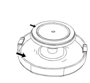
Illustration 50
g00285520
Cooling system filler cap
Pressurized System: Hot coolant can cause seri-
ous burns. To open the cooling system filler cap,
stop the engine and wait until the cooling system
components are cool. Loosen the cooling system
pressure cap slowly in order to relieve the
pressure.
1. Remove the cooling system filler cap slowly in
order to relieve pressure.
2. Maintain the coolant level at the maximum mark
that is correct for your application. If the engine is
equipped with a sight glass, maintain the coolant
level to the correct level in the sight glass.
3. Clean the cooling system filler cap and inspect the
gasket. If the gasket is damaged, discard the old
filler cap and install a new filler cap. If the gasket is
not damaged, use a suitable pressurizing pump in
order to pressure test the filler cap. The correct
pressure is stamped on the face of the filler cap. If
the filler cap does not retain the correct pressure,
install a new filler cap.
Illustration 49
g02590196
Filler cap
This document is printed from SPI². Not for RESALE
![]()
![]()
![]()
![]()
![]()
![]()
![]()
![]()
![]()
![]()
![]()
82
SEBU8609
Maintenance Recommendations
Coolant Temperature Regulator - Replace
4. Inspect the cooling system for leaks.
i03644948
Cooling System Supplemental
Coolant Additive (SCA) - Test/
Add
i05160120
Coolant Temperature
Regulator - Replace
Replace the water temperature regulator before the
water temperature regulator fails. This is a
recommended preventive maintenance practice.
Replacing the water temperature regulator reduces
the chances for unscheduled downtime.
Cooling system coolant additive contains alkali.
To help prevent personal injury, avoid contact
with the skin and the eyes. Do not drink cooling
system coolant additive.
A water temperature regulator that fails in a partially
opened position can cause overheating or
overcooling of the engine.
Test for SCA Concentration
A water temperature regulator that fails in the closed
position can cause excessive overheating. Excessive
overheating could result in cracking of the cylinder
head or piston seizure problems.
Heavy-Duty Coolant/Antifreezeand SCA
NOTICE
Do not exceed the recommended six percent supple-
mental coolant additive concentration.
A water temperature regulator that fails in the open
position will cause the engine operating temperature
to be too low during partial load operation. Low
engine operating temperatures during partial loads
could cause an excessive carbon buildup inside the
cylinders. This excessive carbon buildup could result
in an accelerated wear of the piston rings and wear of
the cylinder liner.
Use a Coolant Conditioner Test Kit in order to check
the concentration of the SCA.
Add the SCA, If Necessary
NOTICE
NOTICE
Failure to replace your water temperature regulator
on a regularly scheduled basis could cause severe
engine damage.
Do not exceed the recommended amount of supple-
mental coolant additive concentration. Excessive sup-
plemental coolant additive concentration can form
deposits on the higher temperature surfaces of the
cooling system, reducing the engine's heat transfer
characteristics. Reduced heat transfer could cause
cracking of the cylinder head and other high tempera-
ture components. Excessive supplemental coolant
additive concentration could also result in radiator
tube blockage, overheating, and/or accelerated water
pump seal wear. Never use both liquid supplemental
coolant additive and the spin-on element (if equipped)
at the same time. The use of those additives together
could result in supplemental coolant additive concen-
tration exceeding the recommended maximum.
Perkins
engines incorporate a shunt design cooling
system and require operating the engine with a water
temperature regulator installed.
If the water temperature regulator is installed incor-
rectly, the engine may overheat, causing cylinder
head damage. Ensure that the new water tempera-
ture regulator is installed in the original position. En-
sure that the water temperature regulator vent hole is
open.
Do not use liquid gasket material on the gasket or cyl-
inder head surface.
Refer to the Disassembly and Assembly Manual,
“Water Temperature Regulator - Remove and Install”
for the replacement procedure of the water
temperature regulator, or consult your Perkins
dealer or your Perkins distributor.
Pressurized System: Hot coolant can cause seri-
ous burns. To open the cooling system filler cap,
stop the engine and wait until the cooling system
components are cool. Loosen the cooling system
pressure cap slowly in order to relieve the
pressure.
Note: If only the water temperature regulators are
replaced, drain the coolant from the cooling system to
a level that is below the water temperature regulator
housing.
This document is printed from SPI². Not for RESALE
![]()
![]()
![]()
![]()
![]()
![]()
![]()
![]()
![]()
![]()
![]()
SEBU8609
83
Maintenance Recommendations
Crankcase Breather (Canister) - Replace
• The filter element within the crankcase breather
must be serviced at the prescribed service interval.
NOTICE
When any servicing or repair of the engine cooling
system is performed the procedure must be per-
formed with the engine on level ground. This will allow
you to accurately check the coolant level. This will al-
so help in avoiding the risk of introducing an air lock
into the coolant system.
• The correct filter element must be installed before
the engine is operated.
• The installation of the filter element is very
important.
• The quality of the filter element that is installed is
very important.
1. Slowly loosen the cooling system filler cap in order
to relieve the pressure. Remove the cooling
system filler cap.
• The filter element protects the engine from
excessive quantities of oil from entering the
induction system. The filter element also protects
the engine aftertreatment system.
Note: Always discard drained fluids according to local
regulations.
2. If necessary, drain some coolant from the cooling
system into a suitable container in order to allow
space for the extra SCA.
Note: Excessive quantities of oil that enter the
induction system of the engine can rapidly increase
the engine speed without control.
3. Add the correct amount of SCA. Refer to the
Operation and Maintenance Manual, “Refill
Capacities and Recommendations” for more
information on SCA requirements.
4. Clean the cooling system filler cap and inspect the
gasket. If the gasket is damaged, discard the old
filler cap and install a new filler cap. If the gasket is
not damaged, use a suitable pressurizing pump in
order to pressure test the filler cap. The correct
pressure is stamped on the face of the filler cap. If
the filler cap does not retain the correct pressure,
install a new filler cap.
i05199993
Crankcase Breather (Canister)
- Replace
Illustration 51
g03331718
Typical example
1. Ensure that dirt cannot enter the breather
Hot oil and hot components can cause personal
injury. Do not allow hot oil or hot components to
contact the skin.
assembly. Ensure that the outside body of the
breather assembly is clean and free from damage.
Place a container under the breather assembly.
2. Remove clip (3) and remove hose (4) from cap (2).
Remove cap (2) from the main body (1).
NOTICE
Ensure that the engine is stopped before any servic-
ing or repair is performed.
The crankcase breather is a very important
component in order to keep your engine emissions
compliant.
This document is printed from SPI². Not for RESALE
![]()
![]()
![]()
![]()
![]()
![]()
![]()
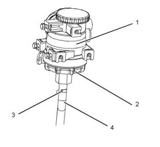
![]()
![]()
84
,S, EBU8609
Maintenance Recommendations
Diesel Particulate Filter - Clean
i05153374
Diesel Particulate Filter - Clean
Wear goggles, gloves, protective clothing, and a
National Institute for Occupational Safety and
Health (NIOSH) approved P95 or N95 half-face res-
pirator when handling a used Diesel Particulate
Filter or Catalytic Converter Muffler. Failure to do
so could result in personal injury.
The muffler, catalytic converter/muffler, and diesel
particulate filter will become extremely hot during
engine operation. A hot muffler, catalytic convert-
er/muffler and diesel particulate filter can cause
serious burns. Allow adequate cooling time be-
fore working on or near the muffler, catalytic con-
verter/muffler and diesel particulate filter.
Illustration 52
g03331704
Typical example
3. Remove filter element (5) and remove O ring seal
(6) and discard.
Note: Ensure that all parts are clean and free from
dirt.
4. Install a new O ring seal (6) onto the cap (2) and
install a new filter element (5) into the cap (2).
5. Install cap assembly into the main body (1).
Tighten the cap assembly to 10 N·m (7 lb ft).
6. Install hose (4) and clip (3). Remove the container
and clean away any split fluid.
Illustration 53
g02335296
Typical example
Note: Improper cleaning or repair of the Diesel
Particulate Filter (DPF) can damage the DPF and the
engine aftertreatment system. Contact your Perkins
dealer for more information.
The DPF is enclosed within the assembly (1). For
information on removal of the DPF, refer to
Disassembly and Assembly, “DPF - Remove”.
This document is printed from SPI². Not for RESALE
![]()
![]()
![]()
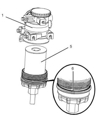
![]()
![]()
![]()
![]()
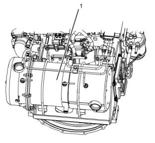
![]()
![]()
SEBU8609
85
Maintenance Recommendations
Engine - Clean
• The DPF on the three cylinder engine is different
from the four cylinder engine.
Aftertreatment
During the engine cleaning process, ensure that
water or cleaning fluids cannot enter the
aftertreatment system. If cleaning fluids enters the
aftertreatment system, damage could occur.
• Only ultra low sulfur diesel fuel can be used in an
application that has an aftertreatment regeneration
device. The use of other fuel will damage your
engine system.
i05160996
• The engine must be operated on CJ-4
specification of engine oil.
Engine Air Cleaner Element -
Replace
i03991933
Engine - Clean
The air cleaner may be installed by the Original
Equipment Manufacture (OEM). Refer to the OEM for
instruction on how to remove the element within the
air cleaner.
i02335405
Personal injury or death can result from high
voltage.
Engine Air Cleaner Service
Indicator - Inspect
Moisture
can
create
paths
of
electrical
conductivity.
Make sure that the electrical system is OFF. Lock
out the starting controls and tag the controls “DO
NOT OPERATE” .
Some engines may be equipped with a different
service indicator.
Some engines are equipped with a differential gauge
for inlet air pressure. The differential gauge for inlet
air pressure displays the difference in the pressure
that is measured before the air cleaner element and
the pressure that is measured after the air cleaner
element. As the air cleaner element becomes dirty,
the pressure differential rises. If your engine is
equipped with a different type of service indicator,
follow the OEM recommendations in order to service
the air cleaner service indicator.
NOTICE
Accumulated grease and oil on an engine is a fire
hazard. Keep the engine clean. Remove debris and
fluid spills whenever a significant quantity accumu-
lates on the engine.
Periodic cleaning of the engine is recommended.
Steam cleaning the engine will remove accumulated
oil and grease. A clean engine provides the following
benefits:
The service indicator may be mounted on the air
cleaner element or in a remote location.
• Easy detection of fluid leaks
• Maximum heat transfer characteristics
• Ease of maintenance
Note: Caution must be used in order to prevent
electrical components from being damaged by
excessive water when the engine is cleaned.
Pressure washers and steam cleaners should not be
directed at any electrical connectors or the junction of
cables into the rear of the connectors. Avoid electrical
components such as the alternator, the starter, and
the ECM. Protect the fuel injection pump from fluids in
order to wash the engine.
Illustration 54
g00103777
Typical service indicator
This document is printed from SPI². Not for RESALE
![]()
![]()
![]()
![]()
![]()
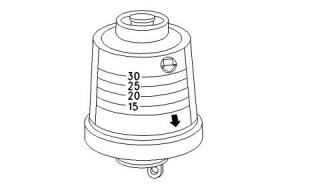
![]()
![]()
86
SEBU8609
Maintenance Recommendations
Engine Air Precleaner - Check/Clean
Observe the service indicator. The air cleaner
element should be cleaned or the air cleaner element
should be replaced when one of the following
conditions occur:
Note: When the engine is operated in dusty
applications, more frequent cleaning is required.
i02323089
• The yellow diaphragm enters the red zone.
• The red piston locks in the visible position.
Engine Mounts - Inspect
Test the Service Indicator
Note: The engine mounts may not have been
supplied by Perkins . Refer to the OEM information
for further information on the engine mounts and the
correct bolt torque.
Service indicators are important instruments.
• Check for ease of resetting. The service indicator
should reset in less than three pushes.
Inspect the engine mounts for deterioration and for
correct bolt torque. Engine vibration can be caused
by the following conditions:
• Check the movement of the yellow core when the
engine is accelerated to the engine rated speed.
The yellow core should latch at the greatest
vacuum that is attained.
• Incorrect mounting of the engine
• Deterioration of the engine mounts
• Loose engine mounts
If the service indicator does not reset easily, or if the
yellow core does not latch at the greatest vacuum,
the service indicator should be replaced. If the new
service indicator will not reset, the hole for the service
indicator may be restricted.
Any engine mount that shows deterioration should be
replaced. Refer to the OEM information for the
recommended torques.
The service indicator may need to be replaced
frequently in environments that are severely dusty.
i05164949
i02927289
Engine Oil Level - Check
Engine Air Precleaner - Check/
Clean
Hot oil and hot components can cause personal
injury. Do not allow hot oil or hot components to
contact the skin.
Illustration 55
g01453058
Typical engine air precleaner
(1) Wing nut
(2) Cover
(3) Body
Remove wing nut (1) and cover (2). Check for an
accumulation of dirt and debris in body (3). Clean the
body, if necessary.
After cleaning the precleaner, install cover (2) and
wing nut (1).
This document is printed from SPI². Not for RESALE
![]()
![]()
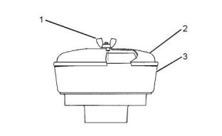
![]()
![]()
![]()
SEBU8609
87
Maintenance Recommendations
Engine Oil and Filter - Change
i05153469
Engine Oil and Filter - Change
Hot oil and hot components can cause personal
injury. Do not allow hot oil or hot components to
contact the skin.
NOTICE
Care must be taken to ensure that fluids are con-
tained during performance of inspection, mainte-
nance, testing, adjusting and repair of the product. Be
prepared to collect the fluid with suitable containers
before opening any compartment or disassembling
any component containing fluids.
Dispose of all fluids according to local regulations and
mandates.
Illustration 56
g03317856
(Y) “ADD” mark. (X) “FULL” mark.
(A) Original oil level gauge
(B) Alternative oil level gauge
NOTICE
Keep all parts clean from contaminants.
NOTICE
Perform this maintenance with the engine stopped.
Contaminants may cause rapid wear and shortened
component life.
Do not drain the oil when the engine is cold. As the oil
cools, suspended waste particles settle on the bottom
of the oil pan. The waste particles are not removed
with the draining cold oil. Drain the crankcase with the
engine stopped. Drain the crankcase with the oil
warm. This draining method allows the waste
particles that are suspended in the oil to be drained
correctly.
Note: Oil gauge (A) or oil gauge (B) may be installed
in the engine.
1. Maintain the oil level between “ADD” mark (Y) and
“FULL” mark (X) on oil level gauge (1). Do not fill
the crankcase above “FULL” mark (X).
NOTICE
Failure to follow this recommended procedure will
cause the waste particles to be recirculated through
the engine lubrication system with the new oil.
Operating your engine when the oil level is above the
“FULL” mark could cause your crankshaft to dip into
the oil. The air bubbles created from the crankshaft
dipping into the oil reduces the oil's lubricating char-
acteristics and could result in the loss of power.
Drain the Engine Oil
After the engine has been run at the normal operating
temperature, stop the engine. Use one of the
following methods to drain the engine crankcase oil:
2. Remove the oil filler cap and add oil, if necessary.
Clean the oil filler cap. Install the oil filler cap.
• If the engine is equipped with a drain valve, turn
the drain valve knob counterclockwise in order to
drain the oil. After the oil has drained, turn the
drain valve knob clockwise in order to close the
drain valve.
• If the engine is not equipped with a drain valve,
remove the oil drain plug in order to allow the oil to
drain. After the oil has drained, the oil drain plug
should be cleaned and installed.
This document is printed from SPI². Not for RESALE
![]()
![]()
![]()
![]()
![]()
![]()
![]()
![]()
![]()
![]()
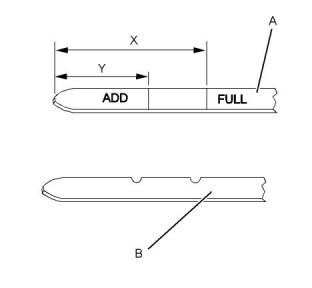
![]()
![]()
![]()
88
SEBU8609
Maintenance Recommendations
Engine Oil and Filter - Change
Replace the Oil Filter
NOTICE
Perkins oil filters are built to Perkins specifications.
Use of an oil filter not recommended by Perkins
could result in severe engine damage to the engine
bearings, crankshaft, etc., as a result of the larger
waste particles from unfiltered oil entering the engine
lubricating system. Only use oil filters recommended
by Perkins .
1. Remove the oil filter with a suitable tool.
Note: The following actions can be carried out as part
of the preventive maintenance program.
2. Cut the oil filter open with a suitable tool. Break
apart the pleats and inspect the oil filter for metal
debris. An excessive amount of metal debris in the
oil filter may indicate early wear or a pending
failure.
Illustration 57
g01334593
Use a magnet to differentiate between the ferrous
metals and the nonferrous metals that are found in
the oil filter element. Ferrous metals may indicate
wear on the steel and cast iron parts of the engine.
(1) Oil cooler
(2) Adapter
(3) Oil filter
Note: The oil cooler (1) and the adapter (2) are
installed on engines that have a turbocharger.
3. Clean the sealing surface of the cylinder block or
the oil cooler (1).
Nonferrous metals may indicate wear on the
aluminum parts, brass parts, or bronze parts of the
engine. Parts that may be affected include the
following items: main bearings, rod bearings,
turbocharger bearings and cylinder heads.
4. Apply clean engine oil to the new oil filter seal (3).
Due to normal wear and friction, it is not
uncommon to find small amounts of debris in the
oil filter. Consult your Perkins dealer or your
Perkins distributor in order to arrange for a further
analysis if an excessive amount of debris is found
in the oil filter.
NOTICE
Do not fill the oil filters with oil before installing them.
This oil would not be filtered and could be contami-
nated. Contaminated oil can cause accelerated wear
to engine components.
5. Install the oil filter. Tighten the oil filter by hand. Do
not overtighten the oil filter.
Fill the Engine Crankcase
1. Remove the oil filler cap. Refer to the Operation
and Maintenance Manual for more information on
lubricant specifications. Fill the crankcase with the
correct amount of oil. Refer to the Operation and
Maintenance Manual for more information on refill
capacities.
NOTICE
If equipped with an auxiliary oil filter system or a re-
mote oil filter system, follow the OEM or filter manu-
facturer's recommendations. Under filling or overfilling
the crankcase with oil can cause engine damage.
This document is printed from SPI². Not for RESALE
![]()
![]()
![]()
![]()
![]()
![]()
![]()
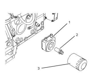
![]()
![]()
SEBU8609
89
Maintenance Recommendations
Engine Valve Lash - Check
NOTICE
NOTICE
To prevent crankshaft bearing damage, crank the en-
gine with the fuel OFF. This will fill the oil filters before
starting the engine. Do not crank the engine for more
than 30 seconds.
Only qualified service personnel should perform this
maintenance. Refer to the Service Manual or your au-
thorized Perkins dealer or your Perkins
distributor
for the complete valve lash adjustment procedure.
Operation of Perkins engines with incorrect valve
lash can reduce engine efficiency, and also reduce
engine component life.
2. Start the engine and run the engine at “LOW IDLE”
for 2 minutes. Perform this procedure in order to
ensure that the lubrication system has oil and that
the oil filters are filled. Inspect the oil filter for oil
leaks.
3. Stop the engine and allow the oil to drain back to
the sump for a minimum of 10 minutes.
Ensure that the engine can not be started while
this maintenance is being performed. To help pre-
vent possible injury, do not use the starting motor
to turn the flywheel.
Hot engine components can cause burns. Allow
additional time for the engine to cool before meas-
uring/adjusting valve lash clearance.
Ensure that the engine is stopped before measuring
the valve lash. The engine valve lash can be
inspected and adjusted when the temperature of the
engine is hot or cold.
Refer to Systems Operation, Testing and Adjusting,
“Engine Valve Lash - Inspect/Adjust” for more
information.
Illustration 58
g03306420
(Y) “ADD” mark. (X) “FULL” mark.
(A) Original oil level gauge
(B) Alternative oil level gauge
4. Remove the oil level gauge in order to check the oil
level. Maintain the oil level between the “MIN” and
“MAX” marks on the oil level gauge.
i05153520
Engine Valve Lash - Check
This maintenance is recommended by Perkins as
part of a lubrication and preventive maintenance
schedule in order to help provide maximum engine
life. The maintenance for the valve lash is important in
order to keep the engine compliant.
This document is printed from SPI². Not for RESALE
![]()
![]()
![]()
![]()
![]()
![]()
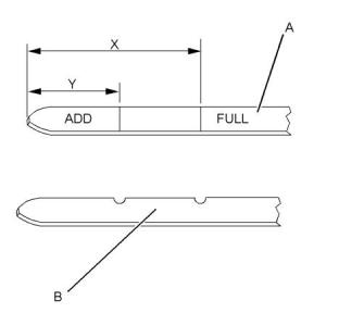
![]()
![]()
![]()
90
SEBU8609
Maintenance Recommendations
Fan Clearance - Check
i05153591
i05161054
Fan Clearance - Check
Fuel Filter (In-Line)- Replace
Fuel leaked or spilled onto hot surfaces or electri-
cal components can cause a fire. To help prevent
possible injury, turn the start switch off when
changing fuel filters or water separator elements.
Clean up fuel spills immediately.
Note: Refer to Systems Operation, Testing, and
Adjusting, “Cleanliness of Fuel System
Components” for detailed information on the
standards of cleanliness that must be observed
during ALL work on the fuel system.
NOTICE
Ensure that the engine is stopped before any servic-
ing or repair is performed.
The location of the in-line fuel filter will depend on the
application that the engine has been installed.
Illustration 59
g03309719
Typical example
Ensure that the engine is stopped. Ensure that the
battery disconnect switch is in the OFF position.
Ensure that the cooling system is full.
The clearance between the cover (2) and the fan (1)
will require checking. The gap between the edge of
the cover and the tip of the fan blade (A) must be
checked in four equally spaced positions.
• (A) equals 5 mm (0.19685 inch) for the three
cylinder engine and the four cylinder naturally
aspirated engine.
• (A) equals 10 mm (0.39370 inch) for the
turbocharged engine.
Illustration 60
g03315616
Arrows show fuel flow
Note: The cover is not adjustable.
Note: The in-line fuel filter is an off engine part.
1. Turn the fuel supply valve (if equipped) to the OFF
position. Remove clamp (3) and remove clamp (6).
2. Remove inlet hose (4) and remove outlet hose (5)
from in-line filter (1).
This document is printed from SPI². Not for RESALE
![]()
![]()
![]()
![]()
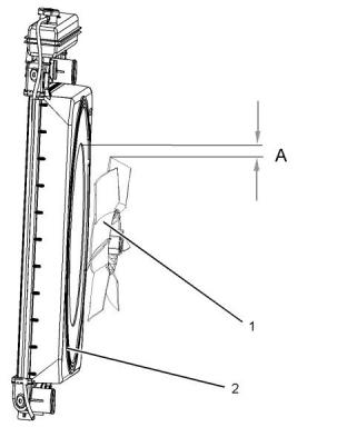
![]()
![]()
![]()
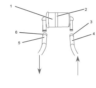
![]()
![]()
SEBU8609
91
Maintenance Recommendations
Fuel Injector - Test/Change
3. If installed, remove clamp (2) and remove in-line
filter (1) from application.
• The engine will not start or the engine is difficult to
start.
• Not enough power
4. Install new in-line filter (1) and install clamp (2).
• The engine misfires or the engine runs erratically.
• High fuel consumption
5. Install inlet hose (4) and install clamp (3). Install
outlet hose (5) and install clamp (6).
6. Turn the fuel supply valve (if equipped) to the ON
position. Prime the system, refer to this Operation
and Maintenance Manual, “Fuel System - Prime”.
• Black exhaust smoke
• The engine knocks or there is vibration in the
engine.
i02154268
• Excessive engine temperature
Fuel Injector - Test/Change
For further information on the removal and the
installation of the fuel injectors, refer to the
Disassembly and Assembly manual.
For further information on the testing of fuel injectors,
refer to the Testing and Adjusting manual.
Identificationof a suspect Fuel
Injector
Fuel leaked or spilled onto hot surfaces or electri-
cal components can cause a fire.
Work carefully around an engine that is running.
Engine parts that are hot, or parts that are mov-
ing, can cause personal injury.
Make sure that you wear eye protection at all
times during testing. When fuel injection nozzles
are tested, test fluids travel through the orifices of
the nozzle tip with high pressure. Under this
amount of pressure, the test fluid can pierce the
skin and cause serious injury to the operator. Al-
ways keep the tip of the fuel injection nozzle
pointed away from the operator and into the fuel
collector and extension.
NOTICE
If your skin comes into contact with high pressure
fuel, obtain medical assistence immediately.
NOTICE
If a fuel injector is suspected of operating outside of
normal parameters it should be removed by a quali-
fied technician. The suspect fuel injector should be
taken to an authorised agent for inspection.
NOTICE
Do not allow dirt to enter the fuel system. Thoroughly
clean the area around a fuel system component that
will be disconnected. Fit a suitable cover over discon-
nected fuel system component.
Operate the engine at a fast idle speed in order to
identify the faulty fuel injector. Individually loosen and
tighten the union nut for the high pressure pipe to
each fuel injector. Do not loosen the union nut more
than half a turn. There will be little effect on the
engine speed when the union nut to the faulty fuel
injector is loosened.
Regular maintenance of the fuel injectors is
recommended by Perkins . The fuel injectors must be
removed and tested by an authorized agent. The fuel
injectors should not be cleaned as cleaning with
incorrect tools can damage the nozzle. The fuel
injectors should be renewed only if a fault with the
fuel injectors occurs. Some of the problems that may
indicate that new fuel injectors are needed are listed
below:
Consult your authorized Perkins dealer or your
Perkins distributor for further assistance.
This document is printed from SPI². Not for RESALE
![]()
![]()
![]()
![]()
![]()
![]()
![]()
![]()
![]()
![]()
![]()
![]()
![]()
92
SEBU8609
Maintenance Recommendations
Fuel System - Prime
i04145953
Fuel System - Prime
Turn the keyswitch to the ON position for 2 minutes in
order to prime the fuel system. Turn keyswitch to OFF
position, then turn on again. The engine is primed
and ready to start.
i05164991
Fuel System Secondary Filter -
Replace
Fuel leaked or spilled onto hot surfaces or electri-
cal components can cause a fire. To help prevent
possible injury, turn the start switch off when
changing fuel filters or water separator elements.
Clean up fuel spills immediately.
Illustration 61
g03317866
Typical example
2. Clean the outside of the fuel filter assembly (1).
3. Remove setscrew (2).
NOTICE
Do not allow dirt to enter the fuel system. Thoroughly
clean the area around a fuel system component that
will be disconnected. Fit a suitable cover over discon-
nected fuel system component.
4. Remove the canister (3). Ensure that any fluid is
drained into a suitable container.
NOTICE
Care must be taken to ensure that fluids are con-
tained during performance of inspection, mainte-
nance, testing, adjusting and repair of the product. Be
prepared to collect the fluid with suitable containers
before opening any compartment or disassembling
any component containing fluids.
Dispose of all fluids according to local regulations and
mandates.
Fuel Filter with Canister
1. Close the fuel supply valve.
Illustration 62
g02710378
Typical example
5. Assemble the following items: seals (8), seal (7),
canister (3) and bowl (10). Place washer (5) and
seal (6) on setscrew (2).
This document is printed from SPI². Not for RESALE
![]()
![]()
![]()
![]()
![]()
![]()
![]()
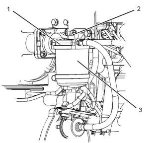
![]()
![]()
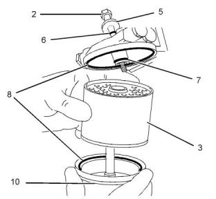
![]()
![]()
SEBU8609
93
Maintenance Recommendations
Fuel Tank Water and Sediment - Drain
6. Fasten the assembly to the fuel filter base with
setscrew (2).
Some fuel tanks use supply pipes that allow water
and sediment to settle below the end of the fuel
supply pipe. Some fuel tanks use supply lines that
take fuel directly from the bottom of the tank. If the
engine is equipped with this system, regular
The fuel system will need to be primed after the new
filter is installed. Refer to this Operation and
Maintenance Manual, “Fuel System - Prime”.
maintenance of the fuel system filter is important.
Fuel Storage Tanks
i02335436
Drain the water and the sediment from the fuel
storage tank at the following intervals:
Fuel Tank Water and Sediment
- Drain
• Weekly
• Service intervals
• Refill of the tank
NOTICE
Care must be taken to ensure that fluids are con-
tained during performance of inspection, mainte-
nance, testing, adjusting and repair of the product. Be
prepared to collect the fluid with suitable containers
before opening any compartment or disassembling
any component containing fluids.
This will help prevent water or sediment from being
pumped from the storage tank into the engine fuel
tank.
If a bulk storage tank has been refilled or moved
recently, allow adequate time for the sediment to
settle before filling the engine fuel tank. Internal
baffles in the bulk storage tank will also help trap
sediment. Filtering fuel that is pumped from the
storage tank helps to ensure the quality of the fuel.
When possible, water separators should be used.
Dispose of all fluids according to local regulations and
mandates.
Fuel Tank
Fuel quality is critical to the performance and to the
service life of the engine. Water in the fuel can cause
excessive wear to the fuel system.
i05154415
Glow Plugs (ARD Combustion)
- Replace
Water can be introduced into the fuel tank when the
fuel tank is being filled.
Condensation occurs during the heating and cooling
of fuel. The condensation occurs as the fuel passes
through the fuel system and the fuel returns to the
fuel tank. This causes water to accumulate in fuel
tanks. Draining the fuel tank regularly and obtaining
fuel from reliable sources can help to eliminate water
in the fuel.
Ensure that all adjustments and repairs are
performed by authorized personnel that have the
correct training.
Drain the Water and the Sediment
Fuel tanks should contain some provision for draining
water and draining sediment from the bottom of the
fuel tanks.
Open the drain valve on the bottom of the fuel tank in
order to drain the water and the sediment. Close the
drain valve.
Check the fuel daily. Allow five minutes after the fuel
tank has been filled before draining water and
sediment from the fuel tank.
Fill the fuel tank after operating the engine in order to
drive out moist air. This will help prevent
condensation. Do not fill the tank to the top. The fuel
expands as the fuel gets warm. The tank may
overflow.
This document is printed from SPI². Not for RESALE
![]()
![]()
![]()
94
SEBU8609
Maintenance Recommendations
Hoses and Clamps - Inspect/Replace
• Cracking
• Softness
• Loose clamps
Replace hoses that are cracked or soft. Tighten any
loose clamps.
NOTICE
Do not bend or strike high pressure lines. Do not in-
stall bent or damaged lines, tubes or hoses. Repair
any loose or damaged fuel and oil lines, tubes and
hoses. Leaks can cause fires. Inspect all lines, tubes
and hoses carefully. Tighten all connections to the
recommended torque. Do not clip any other item to
the high pressure lines.
Check for the following conditions:
• End fittings that are damaged or leaking
• Outer covering that is chafed or cut
Illustration 63
g03310158
Typical example
• Exposed wire that is used for reinforcement
• Outer covering that is ballooning locally
• Flexible part of the hose that is kinked or crushed
• Armoring that is embedded in the outer covering
Remove the Glow Plug for the After
Regeneration Devise (ARD)
1. Ensure that all components are clean and free from
dirt and grease. Remove protective cap (1).
A constant torque hose clamp can be used in place of
any standard hose clamp. Ensure that the constant
torque hose clamp is the same size as the standard
clamp.
2. Remove nut (2) from glow plug (4) and remove
electrical connection (3).
3. Remove glow plug (4) from ARD (5).
Due to extreme temperature changes, the hose will
harden. Hardening of the hoses will cause hose
clamps to loosen. This can result in leaks. A constant
torque hose clamp will help to prevent loose hose
clamps.
Install New Glow Plug
1. Install new glow plug (4) into ARD (5) and tighten
glow plug to a torque of 17 N·m (150 lb in).
Each installation application can be different. The
differences depend on the following factors:
2. Install the electrical connection (3) and install nut
(2). Tighten nut (2) two a torque of 1.5 N·m
(13 lb in).
• Type of hose
• Type of fitting material
3. Install protective cap (1).
• Anticipated expansion and contraction of the hose
i02813964
• Anticipated expansion and contraction of the
fittings
Hoses and Clamps - Inspect/
Replace
Replace the Hoses and the Clamps
Refer to the OEM information for further information
on removing and replacing fuel hoses (if equipped).
Inspect all hoses for leaks that are caused by the
following conditions:
This document is printed from SPI². Not for RESALE
![]()
![]()
![]()
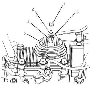
![]()
![]()
SEBU8609
95
Maintenance Recommendations
Radiator - Clean
The coolant system and the hoses for the coolant
system are not usually supplied by Perkins . The
following text describes a typical method of replacing
coolant hoses. Refer to the OEM information for
further information on the coolant system and the
hoses for the coolant system.
Note: Adjust the frequency of cleaning according to
the effects of the operating environment.
Inspect the radiator for these items: Damaged fins,
corrosion, dirt, grease, insects, leaves, oil and other
debris. Clean the radiator, if necessary.
Pressurized System: Hot coolant can cause seri-
ous burns. To open the cooling system filler cap,
stop the engine and wait until the cooling system
components are cool. Loosen the cooling system
pressure cap slowly in order to relieve the
pressure.
Personal injury can result from air pressure.
Personal injury can result without following prop-
er procedure. When using pressure air, wear a
protective face shield and protective clothing.
Maximum air pressure at the nozzle must be less
than 205 kPa (30 psi) for cleaning purposes.
1. Stop the engine. Allow the engine to cool.
Pressurized air is the preferred method for removing
loose debris. Direct the air in the opposite direction to
the fan's air flow. Hold the nozzle approximately 6 mm
(0.25 inch) away from the radiator fins. Slowly move
the air nozzle in a direction that is parallel with the
radiator tube assembly. This will remove debris that is
between the tubes.
2. Loosen the cooling system filler cap slowly in order
to relieve any pressure. Remove the cooling
system filler cap.
Note: Drain the coolant into a suitable, clean
container. The coolant can be reused.
Pressurized water may also be used for cleaning. The
maximum water pressure for cleaning purposes must
be less than 275 kPa (40 psi). Use pressurized water
in order to soften mud. Clean the core from both
sides.
3. Drain the coolant from the cooling system to a level
that is below the hose that is being replaced.
4. Remove the hose clamps.
5. Disconnect the old hose.
Use a degreaser and steam for removal of oil and
grease. Clean both sides of the core. Wash the core
with detergent and hot water. Thoroughly rinse the
core with clean water.
6. Replace the old hose with a new hose.
7. Install the hose clamps with a torque wrench.
If the radiator is blocked internally, refer to the OEM
Manual for information regarding flushing the cooling
system.
Note: For the correct coolant, see this Operation and
Maintenance Manual, “Fluid Recommendations”.
8. Refill the cooling system. Refer to the OEM
information for further information on refilling the
cooling system.
After cleaning the radiator, start the engine. Allow the
engine to operate at low idle speed for three to five
minutes. Accelerate the engine to high idle. This will
help in the removal of debris and the drying of the
core. Slowly reduce the engine speed to low idle and
then stop the engine. Use a light bulb behind the core
in order to inspect the core for cleanliness. Repeat
the cleaning, if necessary.
9. Clean the cooling system filler cap. Inspect the
cooling system filler cap's seals. Replace the
cooling system filler cap if the seals are damaged.
Install the cooling system filler cap.
Inspect the fins for damage. Bent fins may be opened
with a “comb”. Inspect these items for good condition:
Welds, mounting brackets, air lines, connections,
clamps and seals. Make repairs, if necessary.
10. Start the engine. Inspect the cooling system for
leaks.
i02335774
Radiator - Clean
The radiator is not usually supplied by Perkins . The
following text describes a typical cleaning procedure
for the radiator. Refer to the OEM information for
further information on cleaning the radiator.
This document is printed from SPI². Not for RESALE
![]()
![]()
![]()
![]()
![]()
96
SEBU8609
Maintenance Recommendations
Radiator Pressure Cap - Clean/Replace
i03639888
Radiator Pressure Cap - Clean/
Replace
A regular visual inspection of the turbocharger is
recommended. Any fumes from the crankcase are
filtered through the air inlet system. Therefore, by-
products from oil and from combustion can collect in
the turbocharger compressor housing. Over time, this
buildup can contribute to loss of engine power,
increased black smoke and overall loss of engine
efficiency.
If the turbocharger fails during engine operation,
damage to the turbocharger compressor wheel and/
or to the engine may occur. Damage to the
turbocharger compressor wheel can cause additional
damage to the pistons, the valves, and the cylinder
head.
Pressurized System: Hot coolant can cause seri-
ous burns. To open the cooling system filler cap,
stop the engine and wait until the cooling system
components are cool. Loosen the cooling system
pressure cap slowly in order to relieve the
pressure.
NOTICE
Turbocharger bearing failures can cause large quanti-
ties of oil to enter the air intake and exhaust systems.
Loss of engine lubricant can result in serious engine
damage.
NOTICE
When any servicing or repair of the engine cooling
system is performed the procedure must be per-
formed with the engine on level ground. This will allow
you to accurately check the coolant level. This will al-
so help in avoiding the risk of introducing an air lock
into the coolant system.
Minor leakage of oil into a turbocharger under ex-
tended low idle operation should not cause problems
as long as a turbocharger bearing failure has not
occurred.
When a turbocharger bearing failure is accompanied
by a significant loss of engine performance, do not
continue engine operation until the turbocharger is
renewed.
1. Stop the engine and allow the engine to cool.
Loosen the cooling system filler cap slowly in order
to relieve any pressure. Remove the radiator
pressure cap.
A visual inspection of the turbocharger can minimize
unscheduled downtime. A visual inspection of the
turbocharger can also reduce the chance for potential
damage to other engine parts.
2. Check coolant level. Refer to Operation and
Maintenance Manual, “Cooling System Coolant
Level - Check”.
3. Install new radiator pressure cap.
Removal and Installation
For options regarding the removal, installation, and
replacement, consult your Perkins dealer or your
Perkins distributor. Refer to the Disassembly and
Assembly Manual, “Turbocharger - Remove and
Turbocharger - Install” for further information.
i02177969
Starting Motor - Inspect
Perkins recommends a scheduled inspection of the
starting motor. If the starting motor fails, the engine
may not start in an emergency situation.
Inspecting
NOTICE
The compressor housing for the turbocharger must
not be removed from the turbocharger for cleaning.
Check the starting motor for correct operation. Check
the electrical connections and clean the electrical
connections. Refer to the Systems Operation, Testing
and Adjusting Manual, “Electric Starting System -
Test” for more information on the checking procedur, e
<, P>and for specifications or consult your Perkins dealeror your Perkins distributor for assistance.
The actuator linkage is connected to the compressor
housing. If the actuator linkage is moved or disturbed,
the engine may not comply with emissions legislation.
i05157183
Turbocharger - Inspect
(If Equipped)
This document is printed from SPI². Not for RESALE
![]()
![]()
![]()
![]()
![]()
![]()
![]()
![]()
![]()
SEBU8609
97
Maintenance Recommendations
Walk-Around Inspection
1. Remove the pipe from the turbocharger exhaust
outlet and remove the air intake pipe to the
turbocharger. Visually inspect the piping for the
presence of oil. Clean the interior of the pipes in
order to prevent dirt from entering during
reassembly.
NOTICE
Accumulated grease and/or oil on an engine is a fire
hazard. Remove the accumulated grease and oil. Re-
fer to this Operation and Maintenance Manual, “En-
gine - Clean” for more information.
2. Check for the presence of oil. If oil is leaking from
the back side of the compressor wheel, there is a
possibility of a failed turbocharger oil seal.
• Ensure that the cooling system hoses are correctly
clamped and that the cooling system hoses are
tight. Check for leaks. Check the condition of all
pipes.
The presence of oil may be the result of extended
engine operation at low idle. The presence of oil
may also be the result of a restriction of the line for
the intake air (clogged air filters), which causes the
turbocharger to slobber.
• Inspect the water pump for coolant leaks.
Note: The water pump seal is lubricated by the
coolant in the cooling system. It is normal for a small
amount of leakage to occur as the engine cools down
and the parts contract.
3. Inspect the bore of the housing of the turbine outlet
for corrosion.
Excessive coolant leakage may indicate the need to
replace the water pump seal. For the removal of the
water pump and the installation of water pump and/or
seal, refer to the Disassembly and Assembly Manual,
“Water Pump - Remove and Install” for more
information or consult your Perkins dealer or your
Perkins distributor.
4. Fasten the air intake pipe and the exhaust outlet
pipe to the turbocharger housing.
i02177973
Walk-Around Inspection
• Inspect the lubrication system for leaks at the front
crankshaft seal, the rear crankshaft seal, the oil
pan, the oil filters and the rocker cover.
Inspect the Engine for Leaks and
for Loose Connections
• Inspect the fuel system for leaks. Look for loose
fuel line clamps and/or tie-wraps.
A walk-around inspection should only take a few
minutes. When the time is taken to perform these
checks, costly repairs and accidents can be avoided.
• Inspect the piping for the air intake system and the
elbows for cracks and for loose clamps. Ensure
that hoses and tubes are not contacting other
hoses, tubes, wiring harnesses, etc.
For maximum engine service life, make a thorough
inspection of the engine compartment before starting
the engine. Look for items such as oil leaks or coolant
leaks, loose bolts, worn belts, loose connections and
trash buildup. Make repairs, as needed:
• Inspect the alternator belts and any accessory
drive belts for cracks, breaks or other damage.
Belts for multiple groove pulleys must be replaced as
matched sets. If only one belt is replaced, the belt will
carry more load than the belts that are not replaced.
The older belts are stretched. The additional load on
the new belt could cause the belt to break.
• The guards must be in the correct place. Repair
damaged guards or replace missing guards.
• Wipe all caps and plugs before the engine is
serviced in order to reduce the chance of system
contamination.
NOTICE
For any type of leak (coolant, lube, or fuel) clean up
the fluid. If leaking is observed, find the source and
correct the leak. If leaking is suspected, check the flu-
id levels more often than recommended until the leak
is found or fixed, or until the suspicion of a leak is
proved to be unwarranted.
This document is printed from SPI². Not for RESALE
![]()
![]()
![]()
![]()
![]()
98
SEBU8609
Maintenance Recommendations
Water Pump - Inspect
• Drain the water and the sediment from the fuel
tank on a daily basis in order to ensure that only
clean fuel enters the fuel system.
• Inspect the wiring and the wiring harnesses for
loose connections and for worn wires or frayed
wires.
• Inspect the ground strap for a good connection
and for good condition.
• Disconnect any battery chargers that are not
protected against the current drain of the starting
motor. Check the condition and the electrolyte
level of the batteries, unless the engine is
equipped with a maintenance free battery.
• Check the condition of the gauges. Replace any
gauges that are cracked. Replace any gauge that
can not be calibrated.
i01907756
Water Pump - Inspect
A failed water pump may cause severe engine
overheating problems that could result in the following
conditions:
• Cracks in the cylinder head
• A piston seizure
• Other potential damage to the engine
Note: The water pump seal is lubricated by the
coolant in the cooling system. It is normal for a small
amount of leakage to occur as the engine cools down
and parts contract.
Visually inspect the water pump for leaks. Renew the
water pump seal or the water pump if there is an
excessive leakage of coolant. Refer to the
Disassembly and Assembly Manual, “Water Pump -
Remove and Install” for the disassembly and
assembly procedure.
This document is printed from SPI². Not for RESALE
![]()
SEBU8609
99
Warranty Section
Federal Emission Control Warranty
Warranty Section
As a condition of reimbursement, replaced parts and
receipted invoices must be presented at a place of
business of a Perkins distributor or your Perkins
dealer or other establishment authorized by Perkins
Engine Company limited
Warranty Information
This warranty covers the following emission-related
parts and components:
i04059789
Federal Emission Control
Warranty
• Turbocharger System
• Inlet Manifold
• Fuel Injection System
Emissions Warranty
• Crankcase Ventilation System
• Electronic Engine Control System
• Engine Aftertreatment System
• NOxReduction System
The 400F diesel engines are an nonroad
compression ignition engine . Perkins Engine
Company limited warrants to the initial owner and to
the subsequent owner of the 400F diesel engines
that such an engine is:
• AftertreatmentRegeneration Device
1. Designed, built, and equipped so that the engine
conforms, at the time of sale, with all applicable
regulations adopted by the United States
• Miscellaneous valves, switches, hoses, clamps,
connectors, tubing, and sealing devices that are
used in the above systems
Environmental Protection Agency (EPA) .
2. Free from defects in materials and workmanship in
specific emission-related parts for the following
period:
Limitations and Responsibilities
The warranty is subject to the following conditions:
• The warranty period is for 3000 hours or for 5
years, whichever occurs first, after the date of
delivery to the owner that operates the engine.
Perkins Engine Company limited
Responsibilities
If an emission-related part fails during any of the
warranty periods, the part will be repaired or replaced.
Any such part repaired or replaced under warranty is
warranted for the remainder of the warranty period.
During the emission warranty period, if a defect in
material or workmanship of an emission-related part
or component is found, Perkins Engine Company
limited will provide the following:
During the term of this warranty, Perkins Engine
Company limited will provide through a Perkins
distributor or your Perkins dealer or other
establishment authorized by it, repair or replacement
of any warranted part at no charge to the engine
owner.
• New, Remanufactured or repaired parts and/or
components, approved pursuant to EPA
Regulations, required to correct the defect.
• Reasonable and customary labor, during normal
working hours that is required to make the
warranty repair. Included is the labor in order to
remove an engine and install the engine, if
necessary.
In an emergency, repairs may be performed at any
service establishment, or by the owner, using any
replacement part. It is recommended that emission-
related parts be replaced with genuine Perkins
Engine Company limited parts.
Note: Items that are replaced under this warranty
become the property of Perkins Engine Company
limited .
Perkins Engine Company limited will reimburse the
owner for their expenses, including diagnostic
charges for such an emergency repair. These
expenses shall not exceed the Perkins Engine
Company limited suggested retail price for all
warranted parts replaced, and labor charges based
on Perkins Engine Company limited recommended
time allowance for the warranty repair and the
geographically appropriate hourly labor rate.
Owner Responsibilities
During the emission warranty period, the owner is
responsible for the following items:
This document is printed from SPI². Not for RESALE
![]()
100
SEBU8609
Warranty Information
California Emission Control Warranty Statement
• The costs in order to investigate complaints which
are not caused by a defect in Perkins Engine
Company limited material or Perkins Engine
Company limited workmanship.
Perkins Engines Company Limited warrants to the
initial owner and to the subsequent owner of the 400F
diesel engines that such an engine is:
1. Designed, built, and equipped so that the engine
conforms, at the time of sale, with all applicable
regulations adopted by the California Air
Resources Board (CARB) .
• Providing timely notice of a warrantable failure and
promptly making the product available for repair
Limitations
2. Free from defects in materials and workmanship in
specific emission-related parts for the following
period:
Perkins Engine Company limited is not responsible
for resultant damages to an emission-related part or
component resulting from the following items:
• The warranty period is for 3000 hours or for 5
years, whichever occurs first, after the date of
delivery to the owner that operates the engine .
• Any application or any installation that Perkins
Engine Company limited deems improper.
• Attachments, accessory items, or parts not sold
nor approved by Perkins Engine Company limited
If an emission-related part fails during any of the
warranty periods, the part will be repaired or
replaced. Any such part repaired or replaced under
warranty is warranted for the remainder of the
warranty period.
• Improper engine maintenance, repair, or abuse.
• Use of improper fuel, lubricants, or fluids.
During the term of this warranty, Perkins Engines
Company Limited will provide through a Perkins
distributor or your Perkins dealer or other
establishment authorized by it, repair or
replacement of any warranted part at no charge to
the engine owner.
• Owners unreasonable delay in making the product
available after being notified of a potential product
problem.
This warranty is in addition to Perkins Engine
Company limited standard warranty, applicable to the
engine product involved.
In an emergency, repairs may be performed at any
service establishment, or by the owner, using any
replacement part. It is recommended that
emission-related parts be replaced with genuine
Perkins Engines Company Limited parts.
Remedies under this warranty are limited to the
provision of material and services as specified herein.
Perkins Engine Company limited is not responsible
for incidental or consequential damages, including
but not limited to downtime or loss-of-use of engine.
Perkins Engines Company Limited will reimburse
the owner for their expenses, including diagnostic
charges for such an emergency repair. These
expenses shall not exceed the Perkins Engines
Company Limited suggested retail price for all
warranted parts replaced, and labor charges
based on Perkins Engines Company Limited
recommended time allowance for the warranty
repair and the geographically appropriate hourly
labor rate.
i04059870
California Emission Control
Warranty Statement
Emissions Warranty
As a condition of reimbursement, replaced parts
and receipted invoices must be presented at a
place of business of a Perkins distributor or your
Perkins dealer or other establishment authorized
by Perkins Engines Company Limited.
The 400F engines are a nonroad compression
ignition engine .
The California Air Resources Board (CARB) and
Perkins Engines Company Limited are pleased to
explain the emission control system warranty on both
of these diesel engines.
This warranty covers the following emission-
related parts and components:
• Turbocharger System
• Inlet Manifold
In California, new motor vehicle engines must be
designed, built, and equipped in order to meet the
state's stringent anti-smog standards. Perkins
Engines Company Limited must warrant the
emission control system on your engine for the
duration of time listed below provided, there has not
been any abuse, neglect or improper maintenance of
your engine or your engine aftertreatmentsystem.
• Fuel Injection System
• Crankcase Ventilation System
• Electronic Engine Control System
This document is printed from SPI². Not for RESALE
![]()
SEBU8609
101
Warranty Information
Emissions Warranty Information
• Engine AftertreatmentSystem
• Any application or any installation that Perkins
Engines Company Limited deems improper.
• NOxReduction System
• Attachments, accessory items, or parts not sold
nor approved by Perkins Engines Company
Limited
• Aftertreatment Regeneration Device
• Miscellaneous valves, switches, hoses, clamps,
connectors, tubing, and sealing devices that are
used in the above systems
• Improper engine maintenance, repair, or abuse.
• Use of improper fuel, lubricants, or fluids.
Limitationsand Responsibilities
• Owners unreasonable delay in making the product
available after being notified of a potential product
problem.
The warranty is subject to the following conditions:
This warranty is in addition to Perkins Engines
Company Limited standard warranty, applicable to
the engine product involved.
Perkins Engines Company Limited
Responsibilities
Remedies under this warranty are limited to the
provision of material and services as specified herein.
Perkins Engines Company Limited is not responsible
for incidental or consequential damages, including
but not limited to downtime or loss-of-use of engine.
During the emission warranty period, if a defect in
material or workmanship of an emission-related part
or component is found, Perkins Engines Company
Limited will provide the following:
• New, Remanufactured or repaired parts and/or
components, approved pursuant to (CARB)
Regulations, required to correct the defect.
i05200893
Emissions Warranty
Information
• Reasonable and customary labor, during normal
working hours that is required to make the
warranty repair. This includes labor in order to
remove an engine and install the engine, if
necessary.
The aftertreatmentsystem can be expected to
function properly for the life-time of the engine
(emissions durability period) subject to prescribed
maintenance requirements being followed.
Note: Items that are replaced under this warranty
become the property of Perkins Engines Company
Limited .
• EPA
Protection Agency
United States Environmental
Owner Responsibilities
• CARB
California Air Resources Board
During the emission warranty period, the owner is
responsible for the following items:
Note: The warranty of the engine applies to engines
that are operated within the areas of the world where
the following regulations apply: US EPATier 4
Interim, EU Stage IIIB or Japanese MLIT Step 4. If an
engine is operated in regions of the world where
these regulations do not apply the warranty will be
void. Contact your Perkins dealer or your Perkins
distributor for more information.
• The costs in order to investigate complaints which
are not caused by a defect in Perkins Engines
Company Limited material or Perkins Engines
Company Limited workmanship.
• Providing timely notice of a warrantable failure and
promptly making the product available for repair
Maintenance Recommendations
Limitations
Perkins Engines Company Limited engines are
certified by the EPA and the CARB in order to comply
with exhaust emission standards and gaseous
emission standards that are prescribed by the law at
the time of manufacture.
Perkins Engines Company Limited is not responsible
for resultant damages to an emission-related part or
component resulting from the following items:
This document is printed from SPI². Not for RESALE
![]()
![]()
![]()
102
SEBU8609
Warranty Information
Emissions Warranty Information
Efficiency of the emission control and the engine
performance depends on adherence to proper
operation and maintenance recommendations and
use of recommended fuels and lubricating oils.
According to recommendations, major adjustments
and repairs should be made by your authorized
Perkins distributor or your authorized Perkins
dealer.
fuel consumption, black smoke, misfire and rough
running engine. The fuel injector should be inspected,
tested, and replaced, if necessary. Fuel injectors can
be tested by an authorized Perkins distributor/dealer
.
TURBOCHARGER – Refer to this Operation and
Maintenance Manual, “Turbocharger - Inspect” for
information on inspection of the turbocharger.
Various chemical fuel additives which claim to reduce
visible smoke are available commercially. Although
additives have been used to solve some isolated
smoke problems in the field, additives are not
recommended for general use. The engines should
be certified without smoke depressants according to
federal smoke regulations.
ELECTRONIC ENGINE CONTROL (ECM) – The
ECM is the control computer of the engine. The ECM
provides power to the electronics. The ECM monitors
data that is input from the sensors of the engine. The
ECM acts as a governor in order to control the speed
and the power of the engine.
Take corrective steps immediately after worn parts
which may affect the emissions level are discovered
in order to ensure the proper operation of the
emission control systems. The use of genuine
Perkins components is recommended. If the owner
uses non-Perkins components, then the non-Perkins
components must not adversely affect the emissions
level of the engine.
Erratic behavior of the engine may indicate a need for
repair to the ECM. Your Perkins distributor/dealer is
equipped with the necessary tools, personnel, and
procedures in order to perform this service.
The owner is encouraged to keep adequate
maintenance records. However, the absence of such
records will not invalidate the warranty. Refer to the
Operation and Maintenance Manual, “Maintenance
Log” (Reference Materials Section).
For information on the use of Aftermarket Products
and Perkins Engines, refer to this Operation and
Maintenance Manual, “Engine Description”.
The owner may perform routine maintenance, repairs,
and other work that is outside of the warranty. The
work may be done at any repair facility. Such work
does not need to be performed at a designated
station that is determined by the warranty in order for
the warranty to remain in force.
Regular maintenance intervals with a special
emphasis on the following items are necessary in
order to keep exhaust emissions within acceptable
limits for the useful life of the engine. Refer to the
Operation and Maintenance Manual, “Severe Service
Application - Check” topic (Maintenance Section). If
the engine is operating under severe conditions,
adjust the maintenance schedule accordingly. See
your authorized Perkins distributor/dealer in order to
help analyze your specific application, operating
environment, and maintenance schedule
adjustments.
The following information is an explanation of
maintenance items for emission-related components.
See the Operation and Maintenance Manual,
“Maintenance Interval Schedule” (Maintenance
Section) for the specific interval for the following
items.
ENGINE AFTERTREATMENT SYSTEM – The
Engine Aftertreatment Systems are sensitive to the
type of fuel and lubricants that is used. Also, the
engine aftertreatment systems are sensitive to the
operating schedule. Low quality fuel, lubricants, or
fluids may cause increases in exhaust back pressure
or clogging resulting in loss of power. An authorized
Perkins distributor/dealer can determine if the engine
aftertreatmentsystems require a service.
NOx Reduction System (NRS) – The NRS is
monitored. An authorized Perkins distributor/dealer
can determine if the NRS needs service.
FUEL INJECTORS – Fuel injector tips are subject to
wear as a result of fuel contamination. This damage
can cause the following conditions: an increase in
This document is printed from SPI². Not for RESALE
![]()
SEBU8609
103
Reference Information Section
Engine Protection Plans
Reference Information
Section
www.perkins.com
NOTICE
Dependant upon engine type and application.
Reference Materials
i04224089
Engine Protection Plans
(Extended Service Contract)
Extended Service Contracts-purchased in minutes,
protected for years.
Extended Service Contracts (ESC) protect you from
the stress that unexpected repair work brings to your
life by covering the cost of getting your engine up and
running again. Unlike other extended warranties,
Perkins Platinum ESC protects you against all
component part failures.
Purchase peace of mind from only £0.03 / $0.05 /
euro 0.04 a day and let an ESC make your dreams a
reality.
Why buy an Extended Service Contract?
1. No surprises - total protection from unexpected
repair cost (parts, labor, and travel).
2. Enjoy longer lasting product support from Perkins
global network.
3. Genuine Perkins parts ensure continued engine
performance.
4. Highly trained technicians carry out all repairs.
5. Transferable coverage should you sell your
machine.
Flexible coverage provides the right level of
protection for your Perkins Engine. Coverage can be
extended to 2 years/ 1,000 hours right up to 10 year/
40,000
You can buy an ESC at any time during standard
warranty - even the last day!
Each Perkins Distributor has highly trained and
experienced Perkins Product Support Service
Technicians. The Support Service are equipped, and
available around the clock to get your engine running
again with the minimum of downtime. Buying an ESC
means that you get all this for free.
To purchase an Extended Service Contract, is quick
and simple! Contact your local Perkins Distributor
now and the distributor can provide you with a quote
in minutes. You can locate your nearest Perkins
Distributor by visiting:
This document is printed from SPI². Not for RESALE
![]()
![]()
![]()
104
SEBU8609
Index Section
Index
A
Coolant (ELC) - Change.................................. 79
Drain ............................................................ 79
Fill................................................................. 80
Flush ............................................................ 80
Coolant Level - Check ..................................... 80
Engines With a Coolant Recovery Tank....... 80
Engines Without a Coolant Recovery Tank . 81
Coolant Temperature Regulator - Replace...... 82
Cooling System Supplemental Coolant
Additive (SCA) - Test/Add.............................. 82
Add the SCA, If Necessary.......................... 82
Test for SCA Concentration ......................... 82
Crankcase Breather (Canister) - Replace ....... 83
Crushing Prevention and Cutting Prevention ...11
After Starting Engine........................................ 47
After Stopping Engine...................................... 56
Alarms and Shutoffs ........................................ 30
Alarms.......................................................... 30
Shutoffs........................................................ 30
Testing.......................................................... 30
Alternator - Inspect .......................................... 73
Alternator and Fan Belts - Inspect/Adjust........ 74
Adjustment................................................... 74
Inspection..................................................... 74
Alternator and Fan Belts - Replace.................. 75
B
Battery - Replace............................................. 75
Battery Electrolyte Level - Check .................... 75
Battery or Battery Cable - Disconnect ............. 76
Before Starting Engine ...............................12, 45
Belts - Inspect/Adjust/Replace (Air Pump
Belt)................................................................ 76
Adjust........................................................... 77
Inspection..................................................... 76
Belts - Inspect/Replace (Air Pump belt)........... 77
Burn Prevention................................................. 9
Batteries......................................................... 9
Coolant........................................................... 9
Induction System ........................................... 9
Oils................................................................. 9
D
Diagnostic Lamp.............................................. 43
Diesel Particulate Filter - Clean....................... 84
Diesel Particulate Filter Regeneration............. 48
Modes of Regeneration................................ 49
Regeneration............................................... 48
Regeneration Indicators............................... 48
Regeneration Switch.................................... 49
Soot Level Monitoring and Indicators........... 49
E
Electrical System............................................. 13
Grounding Practices .................................... 13
Emergency Stopping....................................... 56
Emissions Certification Film ............................ 26
Emissions Warranty Information.................... 101
Maintenance Recommendations............... 101
Engine - Clean................................................. 85
Aftertreatment.............................................. 85
Engine Air Cleaner Element - Replace............ 85
Engine Air Cleaner Service Indicator -
Inspect........................................................... 85
Test the Service Indicator............................. 86
Engine Air Precleaner - Check/Clean.............. 86
Engine Diagnostics.......................................... 43
Engine Electronics........................................... 14
Engine Mounts - Inspect.................................. 86
Engine Oil and Filter - Change ........................ 87
Drain the Engine Oil..................................... 87
Fill the Engine Crankcase............................ 88
Replace the Oil Filter.................................... 88
C
California Emission Control Warranty
Statement .................................................... 100
Emissions Warranty................................... 100
Cold Weather Operation.................................. 52
Hints for Cold Weather Operation................ 52
Idling the Engine .......................................... 53
Recommendations for Coolant Warm Up .... 53
Recommendations for the Coolant .............. 53
Viscosity of the Engine Lubrication Oil......... 53
Cold Weather Starting ..................................... 45
Configuration Parameters................................ 44
Coolant (Commercial Heavy-Duty) - Change.. 77
Drain ............................................................ 78
Fill................................................................. 78
Flush ............................................................ 78
This document is printed from SPI². Not for RESALE
![]()
SEBU8609
105
Index Section
Engine Oil Level - Check................................. 86
Engine Operation............................................. 48
Engine Operation and Active Regeneration
................................................................... 48
Reduction of Particulate Emissions ............. 48
Engine Operation with Active Diagnostic
Fuel System - Prime........................................ 92
Fuel System Secondary Filter - Replace......... 92
Fuel Filter with Canister ............................... 92
Fuel Tank Water and Sediment - Drain............ 93
Drain the Water and the Sediment............... 93
Fuel Storage Tanks...................................... 93
Fuel Tank ..................................................... 93
Codes ............................................................ 43
Engine Operation with Intermittent
Diagnostic Codes........................................... 43
Engine Protection Plans (Extended Service
Contract)...................................................... 103
Engine Starting...........................................12, 45
Engine Stopping.........................................13, 56
Engine Valve Lash - Check.............................. 89
G
Gauges and Indicators .................................... 30
AftertreatmentLamps .................................. 31
Indicators and Lamps................................... 31
General Hazard Information.............................. 5
Containing Fluid Spillage............................... 7
Dispose of Waste Properly............................. 8
Fluid Penetration............................................ 7
Inhalation ....................................................... 8
Pressure Air and Water.................................. 7
General Information......................................... 15
Glow Plugs (ARD Combustion) - Replace....... 93
Remove the Glow Plug for the After
F
Fan Clearance - Check.................................... 90
Fault Logging................................................... 43
Features and Controls..................................... 30
Federal Emission Control Warranty................. 99
Emissions Warranty..................................... 99
Fire Prevention and Explosion Prevention ...... 10
Fire Extinguisher...........................................11
Lines, Tubes, and Hoses ..............................11
Regeneration ................................................11
Fluid Recommendations.......................58, 62, 65
Diesel Fuel Characteristics ......................... 67
Diesel Fuel Requirements ........................... 65
ELC Cooling System Maintenance.............. 60
Engine Oil .................................................... 63
General Coolant Information........................ 58
General Information..................................... 65
General Lubricant Information ..................... 62
Foreword............................................................ 4
California Proposition 65 Warning ................. 4
Literature Information..................................... 4
Maintenance.................................................. 4
Maintenance Intervals.................................... 4
Operation....................................................... 4
Overhaul ........................................................ 4
Safety............................................................. 4
Fuel and the Effect from Cold Weather............ 54
Fuel Conservation Practices............................ 50
Fuel Filter (In-Line) - Replace.......................... 90
Fuel Injector - Test/Change.............................. 91
Identification of a suspect Fuel Injector........ 91
Fuel Related Components in Cold Weather.... 55
Fuel Filters ................................................... 55
Fuel Heaters ................................................ 55
Fuel Tanks.................................................... 55
Regeneration Devise (ARD) ...................... 94
H
Hoses and Clamps - Inspect/Replace............. 94
Replace the Hoses and the Clamps ............ 94
I
Important Safety Information............................. 2
L
Lifting and Storage........................................... 28
M
Maintenance Interval Schedule....................... 73
Commissioning............................................ 73
Daily............................................................. 73
Every 1000 Service Hours........................... 73
Every 12 000 Service Hours or 6 Years....... 73
Every 2000 Service Hours........................... 73
Every 250 Service Hours or 6 Months ......... 73
Every 3000 Service Hours........................... 73
Every 3000 Service Hours or 2 Years.......... 73
Every 50 Service Hours or Weekly .............. 73
Every 500 Service Hours............................. 73
This document is printed from SPI². Not for RESALE
![]()
106
SEBU8609
Index Section
Every 500 Service Hours or 1 Year.............. 73
When Required............................................ 73
Maintenance Recommendations..................... 70
Maintenance Section....................................... 57
Model View Illustrations (Engines and
Aftertreatment)............................................... 15
403F-15T ..................................................... 15
404F-22........................................................ 16
404F-22T ..................................................... 17
AftertreatmentSystem................................. 20
Engine with Low Mounted Air Pump............ 22
Off Engine Parts........................................... 21
Monitoring System........................................... 32
ProgrammableOptions and Systems
Refill Capacities............................................... 57
Cooling System............................................ 57
Lubrication System ...................................... 57
S
Safety Messages............................................... 5
(1) Universal Warning .................................... 5
Safety Section ................................................... 5
Self-Diagnostics............................................... 43
Sensors and Electrical Components
(Engine and Aftertreatment) .......................... 33
Severe Service Application.............................. 71
Environmental Factors................................. 71
Incorrect Maintenance Procedures.............. 72
Incorrect Operating Procedures................... 72
Starting Motor - Inspect ................................... 96
Starting the Engine.......................................... 46
Starting the Engine ...................................... 46
Starting with Jump Start Cables ...................... 46
Stopping the Engine ........................................ 56
System Pressure Release............................... 70
Coolant System............................................ 70
Engine Oil .................................................... 70
Fuel System................................................. 70
Operation ................................................... 32
Monitoring System (Engine Warning
Indicators)...................................................... 33
Mounting and Dismounting.............................. 12
O
Operation Section............................................ 28
Overspeed....................................................... 33
P
Plate Locations and Film Locations................. 26
Product Description......................................... 22
AftermarketProducts and Perkins Engines
................................................................... 25
Electronic Engine Features.......................... 24
Engine Diagnostics...................................... 24
Engine Service Life...................................... 24
Engine Specifications .................................. 23
Product Identification Information.................... 26
Product Information Section ............................ 15
Product Lifting.................................................. 28
Lifting Eyes with Top Mounted Aftertreatment
................................................................... 28
Product Storage (Engine and
T
Table of Contents............................................... 3
Turbocharger - Inspect (If Equipped)............... 96
Inspecting..................................................... 96
Removal and Installation.............................. 96
W
Walk-Around Inspection .................................. 97
Inspect the Engine for Leaks and for Loose
Connections............................................... 97
Warranty Information....................................... 99
Warranty Section............................................. 99
Water Pump - Inspect...................................... 98
Welding on Engines with Electronic Controls.. 70
Aftertreatment)............................................... 28
Condition for Storage................................... 28
R
Radiator - Clean............................................... 95
Radiator Pressure Cap - Clean/Replace......... 96
Reference Information..................................... 27
Record for Reference................................... 27
Reference InformationSection...................... 103
Reference Materials ...................................... 103
This document is printed from SPI². Not for RESALE
![]()
Product and Dealer Information
Note: For
product identification plate locations, see the section “Product Identification
Information” in the Operation and Maintenance Manual.
Delivery Date:
Product Information
Model:
Product Identification Number:
Engine Serial Number:
Transmission
Serial Number:
Generator Serial Number:
Attachment Serial Numbers:
Attachment Information:
Customer Equipment Number:
Dealer Equipment
Number:
Dealer Information
Name:
Branch:
Address:
Dealer
Phone
Hours
Contact
Number
Sales:
Parts:
Service:
This document is printed from SPI². Not for RESALE
![]()
![]()
![]()
![]()
![]()
![]()
![]()
![]()
![]()
![]()
![]()
![]()
![]()
![]()
![]()
![]()
![]()
![]()
![]()
![]()
![]()
![]()
![]()
![]()
![]()
©2013Perkins Engines Company Limited
All Rights Reserved
This document is printed from SPI². Not for RESALE
免費熱線
400-100-8969???15088860848
400-100-8969???15088860848
機組銷售
0574-26871589? 15267810868
0574-26871589? 15267810868
配件銷售
0574-26886646? 15706865167
0574-26886646? 15706865167
維修熱線
0574-26871569 18658287286
0574-26871569 18658287286
手機端

微信公眾號