 English
 Espaol
 Franais
 阿拉伯
阿拉伯 中文(簡(jiǎn))
 Deutsch
 Italiano
 Português
 日本
日本 韓國(guó)
 български
 hrvatski
 esky
esky Dansk
Dansk Nederlands
 suomi
suomi Ελληνικ
 印度
印度 norsk
norsk Polski
 Roman
Roman русский
 Svenska
 珀金斯Perkins1104C-E44(T)(TA)技術(shù)資料,珀金斯Perkins1104C-E44(T)(TA)技術(shù)資料技術(shù)支持中心,珀金斯Perkins1104C-E44(T)(TA)技術(shù)資料代理商,珀金斯Perkins1104C-E44(T)(TA)技術(shù)資料銷(xiāo)售服務(wù)中心,珀金斯Perkins1104C-E44(T)(TA)技術(shù)資料價(jià)格規(guī)格資料查詢(xún),寧波日昕動(dòng)力科技有限公司

首頁(yè)
產(chǎn)品展示>珀金斯Perkins1104C-E44(T)(TA)技術(shù)資料(英文)
珀金斯Perkins1104C-E44(T)(TA)技術(shù)資料(英文)
詳細(xì)描述
Specifications
1104E Engine
R F ( Engine)
RH (Engine)
R K ( Engine)
This document has been printed from SPI². Not for Resale
![]()
![]()
![]()
![]()
![]()
i01658146
ImportantSafetyInformation
Mostaccidentsthatinvolveproductoperation,maintenanceandrepairarecausedbyfailuretoobserve
basicsafetyrulesorprecautions.Anaccidentcanoftenbeavoidedbyrecognizingpotentiallyhazardous
situationsbeforeanaccidentoccurs.Apersonmustbealerttopotentialhazards.Thispersonshouldalso
havethenecessarytraining,skillsandtoolstoperformthesefunctionsproperly.
Improperoperation,lubrication,maintenanceorrepairofthisproductcanbedangerousand
couldresultininjuryordeath.
Donotoperateorperformanylubrication,maintenanceorrepaironthisproduct,untilyouhave
readandunderstoodtheoperation,lubrication,maintenanceandrepairinformation.
Safetyprecautionsandwarningsareprovidedinthismanualandontheproduct.Ifthesehazardwarnings
arenotheeded,bodilyinjuryordeathcouldoccurtoyouortootherpersons.
Thehazardsareidentifiedbythe“SafetyAlertSymbol”andfollowedbya“SignalWord”suchas
“DANGER”,“WARNING”or“CAUTION”.TheSafetyAlert“WARNING”labelisshownbelow.
Themeaningofthissafetyalertsymbolisasfollows:
Attention!BecomeAlert!YourSafetyisInvolved.
Themessagethatappearsunderthewarningexplainsthehazardandcanbeeitherwrittenorpictorially
presented.
Operationsthatmaycauseproductdamageareidentifiedby“NOTICE”labelsontheproductandin
thispublication.
Perkins cannot anticipa te e ver y p os sible c irc u mstance t hat m ight invol ve a pote n ti al hazard .
Thewarningsinthispublicationandontheproductare,therefore,notallinclusive.Ifatool,
proc edure, work me thod or ope rating technique tha t is not s pecific ally rec ommended by Perkins
isused,youmustsatisfyyourselfthatitissafeforyouandforothers.Youshouldalsoensurethat
theproductwillnotbedamagedorbemadeunsafebytheoperation,lubrication,maintenanceor
repairproceduresthatyouchoose.
Theinformation,specifications,andillustrationsinthispublicationareonthebasisofinformationthat
wasavailableatthetimethatthepublicationwaswritten.Thespecifications,torques,pressures,
measurements,adjustments,illustrations,andotheritemscanchangeatanytime.Thesechangescan
affecttheservicethatisgiventotheproduct.Obtainthecompleteandmostcurrentinformationbeforeyou
s t ar t any jo b . Perkins dea le rs hav e t he m os t c ur r en t i nfo rm ati on a va il abl e.
When replacement parts are required for this
product Perkinsre comme nds usi ng Perkins
re pl ace ment parts or parts w ith equiva lent
specificationsincluding,butnotlimitedto, phys-
icaldimensions,type,strengthandmaterial.
Failuretoheedthiswarningcanleadtoprema-
turefailures,productdamage,personalinjuryor
death.
This document has been printed from SPI². Not for Resale
![]()
![]()
![]()
SENR9976
3
Table of Contents
Table of Contents
Specifications Section
Engine Design ..................................................... 4
Fuel Injection Lines .............................................. 4
Fuel Injection Pump ............................................. 4
Fuel Injectors ....................................................... 5
Fuel Transfer Pump ............................................. 6
Lifter Group ........................................................... 6
Rocker Shaft ........................................................ 6
Valve Mechanism Cover ...................................... 7
Cylinder Head Valves ........................................... 7
Cylinder Head ...................................................... 9
Turbocharger ....................................................... 10
Exhaust Manifold ................................................. 11
Camshaft ............................................................. 11
Camshaft Bearings .............................................. 12
Engine Oil Filter ................................................... 12
Engine Oil Pump .................................................. 13
Engine Oil Pressure ............................................. 15
Engine Oil Bypass Valve ...................................... 15
Engine Oil Pan ..................................................... 16
Crankcase Breather ............................................. 18
Water Temperature Regulator and Housing ......... 18
Water Pump ......................................................... 19
Cylinder Block ...................................................... 20
Crankshaft ........................................................... 21
Crankshaft Seals ................................................. 23
Connecting Rod Bearing Journal ......................... 24
Main Bearing Journal ............................................ 24
Connecting Rod ................................................... 25
Piston and Rings .................................................. 26
Piston Cooling Jet ................................................. 27
Front Housing and Covers ................................... 28
Gear Group (Front) ............................................... 29
Flywheel ............................................................... 30
Flywheel Housing ................................................ 31
Crankshaft Pulley ................................................. 31
Fan Drive ............................................................. 31
Engine Lifting Bracket ........................................... 32
Alternator ............................................................. 32
Starter Motor ........................................................ 33
Coolant Temperature Sensor ............................... 34
Engine Oil Pressure Sensor ................................. 35
Boost Pressure Sensor ......................................... 35
Inlet Manifold Temperature Sensor ....................... 36
Speed/Timing Sensor .......................................... 36
Voltage Load Protection Module ........................... 37
Electronic Control Module ..................................... 37
Glow Plugs ........................................................... 37
Index Section
Index ..................................................................... 38
This document has been printed from SPI². Not for Resale
![]()
4
SENR9976
Specifications Section
Specifications Section
Engine Design
When the camshaft is viewed from the front of
the engine, the camshaft rotates in the following
direction: ................................................... Clockwise
i02242466
The front of the engine is opposite the flywheel end.
The left side and the right side of the engine are
viewed from the flywheel end. The No. 1 cylinder is
the front cylinder.
Four Cylinder Engine
i01914111
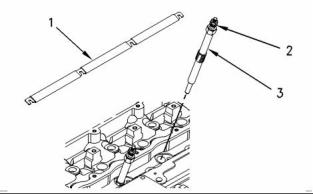
Fuel Injection Lines
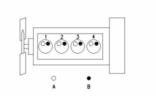
g00984281
Illustration 1
Cylinder and valve location
(A) Inlet valve
(B) Exhaust valve
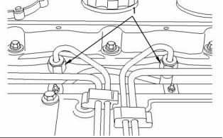
g00923498
Illustration 2
Bore ......................................... 105 mm (4.133 inch)
Stroke ...................................... 127 mm (5.000 inch)
A typical fuel line
(1) Tighten
the union nuts for the fuel injector to the
following torque. ....................... 30 N·m (22 lb ft)
Displacement ...................................... 4.4 L (269 in )
3
Note: Tighten the union nuts at the fuel injection
Cylinder arrangement ..................................... In-line
Type of combustion ............................ Direct injection
Compression ratio
pump to the following torque.30 N·m (22 lb ft)
i02242475
Fuel Injection Pump
Naturally aspirated engines .................... 19.25:1
Turbocharged engines ............................ 18.23:1
Bosch VP30
Number of cylinders ................................................ 4
Valves per cylinder .................................................. 2
Valve lash
Note: Parts that are inside of the fuel injection pump
are only serviceable by an authorized Bosch dealer.
Please consult your parts book for availability of parts
on the outside of the pump that are not related to the
settings of the fuel pump and for the possibility of
remanufacturing options.
Inlet valve ......................... 0.20 mm (0.008 inch)
Exhaust valve ................... 0.45 mm (0.018 inch)
Firing order ................................................. 1, 3, 4, 2
When the crankshaft is viewed from the front of
the engine, the crankshaft rotates in the following
direction: ................................................... Clockwise
This document has been printed from SPI². Not for Resale
![]()
![]()
![]()
![]()
SENR9976
5
Specifications Section
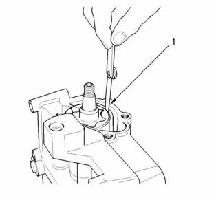
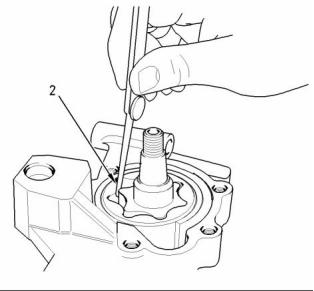
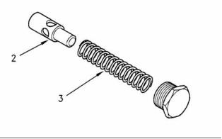
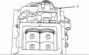
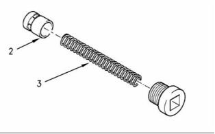
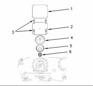
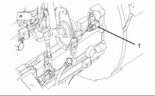
i02207945
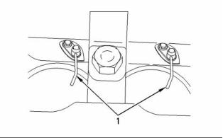
Fuel Injectors
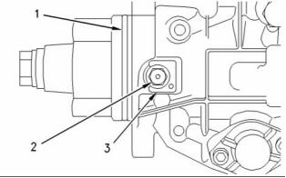
g00925395
Illustration 3
(1) O-ring
Note: Lubricate the O-ring with clean engine oil
before installing the fuel injection pump in the timing
case.
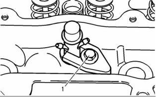
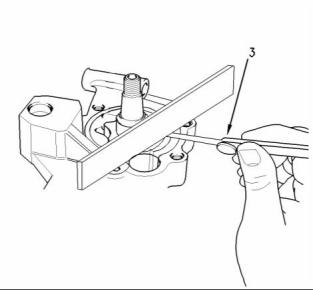
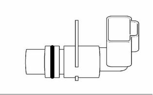
g00908211
Illustration 5
Fuel injector clamp
(2) Locking screw
(1) Tighten the bolt in the clamp for the fuel injector
to the following torque. ............. 35 N·m (26 lb ft)
Unlocked pump shaft
Tighten the locking screw when the spacer is
The fuel injector should be tested at the pressure in
Table 1.
installed to the following torque. .. 12 N·m (9 lb ft)
Locked pump shaft
Leakage in 10 seconds ................................. 0 drops
Tighten the locking screw when the spacer is not
installed to the following torque. .............. 31 N·m
(23 lb ft)
Table 1
Service setting for the Fuel Injector
Injection Pressure
(3) Spacer
29.4 + 0.8 MPa (4264 + 116 psi)
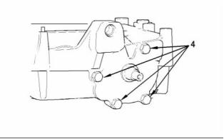
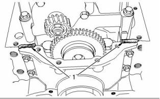
g00925394
Illustration 4
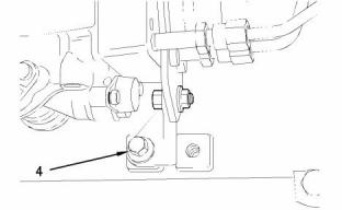
(4) Tighten the bolt for the support bracket to the
following torque. ....................... 44 N·m (32 lb ft)
Note: Ensure that force is not applied to the fuel
injection pump when you are tightening the bolt for
the support bracket.
Tighten the three mounting bolts for the fuel injection
pump to the following torque. .......... 25 N·m (18 lb ft)
This document has been printed from SPI². Not for Resale
![]()
![]()
![]()
![]()
![]()

6
SENR9976
Specifications Section
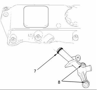
i01957629
i01714153
Fuel Transfer Pump
Lifter Group
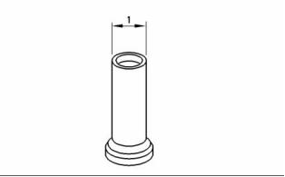
g00629433
Illustration 7
(1) Diameter of the lifter body .... 18.99 to 19.01 mm
(0.7475 to 0.7485 inch)
Clearance of the lifter in the cylinder block
bore ........... 0.04 to 0.09 mm (0.0015 to 0.0037 inch)
i02242607
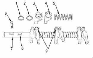
Rocker Shaft
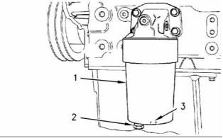
g00986823
Illustration 6
(1) Retaining bolts
(2) Clip
(3) Spacer
(4) Fuel transfer pump
Type .......................... 12 or 24 volt electric motor
(5) Fuel filter element
(6) O ring
g00985174
Illustration 8
The rocker shaft
(7) Fuel filter bowl
Note: Tighten the fuel filter bowl by hand. Rotate the
Note: In order to install the rocker shaft assembly,
the tool 27610227 Spacing Tool is required.
bowl 1/8 of a turn more by hand.
(1) Snap ring
(2) Washer
(3) Rocker arm
(4) Rocker arm bore
This document has been printed from SPI². Not for Resale
![]()
![]()
![]()
![]()
![]()
SENR9976
7
Specifications Section
Diameter of the rocker arm bore for the
i01958092
bushing ................................. 25.01 to 25.05 mm
(0.9847 to 0.9862 inch)
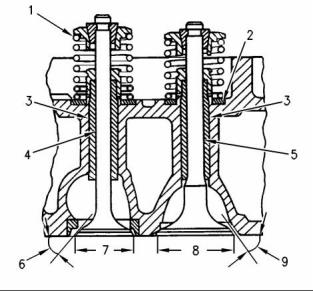
Cylinder Head Valves
Rocker arm bushing
Clearance between the rocker arm bushing and
the rocker shaft ......................... 0.03 to 0.09 mm
(0.0010 to 0.0035 inch)
Maximum permissible clearance between
the rocker arm bushing and the rocker
shaft .................................. 0.17 mm (0.007 inch)
(5) Spring
Note: Install the longest screw at the front of the
rocker shaft assembly.
(6) Tighten the screws evenly. Begin in the center
and work toward the outside. Tighten the screws
to the following torque. ............. 35 N·m (26 lb ft)
(7) Rocker shaft
Diameter of the rocker shaft .. 24.96 to 24.99 mm
(0.9827 to 0.9839 inch)
g00294082
Illustration 10
Cross section of cylinder head
(8) In order to install the rocker shaft assembly,
ensure that the machined square is to the top
of the rocker shaft.
(1) Valve spring
(9) Locknut
Naturally aspirated engines
The installed length of the valve
Torque for the locknut ............... 27 N·m (20 lb ft)
springs .............................. 33.5 mm (1.318 inch)
i01776124
The load for the installed valve springs ..... 254 N
(57.1 lb)
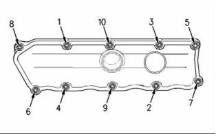
Valve Mechanism Cover
Turbocharged engines
The installed length of the valve
springs .............................. 34.5 mm (1.358 inch)
The load for the installed valve spring ....... 229 N
(51.4 lb)
(2) Valve spring recess
(3) The finished valve guides
Inside diameter of valve
guide ..................................... 9.000 to 9.022 mm
(0.3543 to 0.3552 inch)
Outside diameter of the exhaust valve
guide ................................. 13.034 to 13.047 mm
(0.5131 to 0.5137 inch)
g00908011
Illustration 9
Outside diameter of the inlet valve
guide ................................. 13.034 to 13.047 mm
(0.5131 to 0.5137 inch)
Tighten the bolts for the valve mechanism cover
in the sequence that is shown to the following
torque. ................................................. 9 N·m (7 lb ft)
Interference fit of valve guide in cylinder
head ...................................... 0.007 to 0.047 mm
(0.0003 to 0.0019 inch)
This document has been printed from SPI². Not for Resale
![]()
![]()
![]()
8
SENR9976
Specifications Section
Length of Valve guide .......... 51.00 to 51.50 mm
(2.018 to 2.027 inch)
Service limit ............................ 1.09 mm (0.043 inch)
Turbocharged engines .................... 1.58 to 1.84 mm
(0.062 to 0.072 inch)
Projection of the valve guide above the valve
spring recess (2) ................... 12.35 to 12.65 mm
(0.486 to 0.498 inch)
Service limit .......................... 2.09 mm (0.0823 inch)
(6) Exhaust valve face angle from the vertical axis
Note: When new valve guides are installed, new
valves and new valve seat inserts must be installed.
The valve guides and the valve seat inserts are
supplied as partially finished parts. The unfinished
valve guides and unfinished valve seat inserts are
installed in the cylinder head. The guides and inserts
are then cut and reamed in one operation with special
tooling. This procedure ensures the concentricity
of the valve seat to the valve guide in order to
create a seal that is tight. Refer to the Disassembly
and Assembly Manual for removal and installation
procedures.
Valve face angle ............................... 30 degrees
Valve seat angle ............................... 30 degrees
(7) Diameter of the exhaust
valve head ............................ 41.51 to 41.75 mm
(1.634 to 1.643 inch)
(8) Diameter of the head of the inlet
valve ... 46.20 to 46.45 mm (1.818 to 1.828 inch)
(9) Angle of the inlet valve face from the vertical axis
(4) Exhaust valve
Valve face angle ............................... 30 degrees
Valve seat angle ............................... 30 degrees
Diameter of the exhaust valve
stem ...................................... 8.938 to 8.960 mm
(0.3519 to 0.3528 inch)
The valve lash is the following value when the engine
is cold:
Clearance of valve in valve
Inlet valves ........................ 0.20 mm (0.008 inch)
Exhaust valves ................. 0.45 mm (0.018 inch)
guide ....... 0.040 to 0.840 mm (0.0016 to 0.033 inch)
Overall length of the exhaust
valve ..... 128.92 to 129.37 mm (5.075 to 5.093 inch)
The face of the exhaust valve is recessed below the
cylinder head by the following amount.
Naturally aspirated engines ............ 0.53 to 0.81 mm
(0.021 to 0.032 inch)
Service limit ............................ 1.06 mm (0.042 inch)
Turbocharged engines .................... 1.53 to 1.81 mm
(0.060 to 0.071 inch)
Service limit ........................... 2.06 mm (0.0811 inch)
(5) Inlet valve
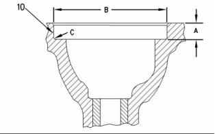
g00809016
Illustration 11
Recess for the valve seat insert
Diameter of the inlet valve
(10) Machine the recess in the head for valve seat
inserts to the following dimensions.
stem ...................................... 8.953 to 8.975 mm
(0.3525 to 0.3533 inch)
Recess for Inlet Valve Seat for Naturally
Aspirated Engines
Clearance of valve in valve
guide .. 0.025 to 0.069 mm (0.001 to 0.0027 inch)
(A) .. 9.910 to 10.040 mm (0.3901 to 0.3952 inch)
(B) ..................................... 47.820 to 47.845 mm
(1.8826 to 1.8836 inch)
Overall length of the inlet
valve ..... 128.92 to 129.37 mm (5.075 to 5.093 inch)
(C) Maximum radius ......... 0.38 mm (0.015 inch)
The face of the inlet valve is recessed below the
cylinder head by the following amount.
Recess for Exhaust Valve Seat for Naturally
Aspirated Engines
(A) .. 9.910 to 10.040 mm (0.3901 to 0.3952 inch)
Naturally aspirated engines ............ 0.58 to 0.84 mm
(0.023 to 0.033 inch)
This document has been printed from SPI². Not for Resale
![]()
![]()
SENR9976
9
Specifications Section
(B) ..................................... 42.420 to 42.445 mm
(1.6701 to 1.6711 inch)
(C) Maximum radius ......... 0.38 mm (0.015 inch)
Recess for Inlet Valve Seat for Turbocharged
Engines
(A) ...................................... 10.910 to 11.040 mm
(0.4295 to 0.4346 inch)
(B) ..................................... 47.820 to 47.845 mm
(1.8826 to 1.8836 inch)
(C) Maximum radius ......... 0.38 mm (0.015 inch)
Recess for Exhaust Valve Seat for Turbocharged
Engines
(A) ...................................... 10.910 to 11.040 mm
(0.4295 to 0.4346 inch)
(B) ..................................... 42.420 to 42.445 mm
(1.6700 to 1.6710 inch)
(C) Maximum radius ......... 0.38 mm (0.015 inch)
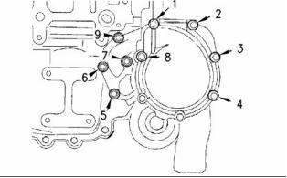
i01899306
g00987480
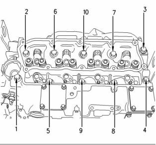
Illustration 12
Cylinder Head
The tightening sequence
Lubricate the threads and the underside of the head
bolts with clean engine oil.
The maximum distortion of the cylinder head is given
in table 3.
Tighten the bolts in the sequence that is shown in
Illustrations to the following torque. ......... 50 N·m
(37 lb ft)
Table 2
Tighten the bolts again to the following
torque. .................................... 100 N·m (74 lb ft)
Required Tools
Part
Part Description
Qty
Number
21825607
Angle gauge
1
The cylinder head bolts are two different lengths. The
following information provides the proper torque for
the cylinder head bolts.
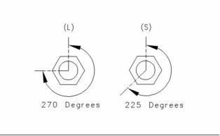
g00905621
Illustration 13
The head bolts require an additional torque turn
procedure. The numbers (1, 3, 4) are three long
cylinder head bolts. All the other bolts are short bolts.
The tightening sequence is shown in the Illustrations .
Place the angle gauge on the top of each bolt
head. Tighten the short bolts to the additional
amount. ........................................... 225 degrees
Place the angle gauge on the top of each bolt
head. Tighten the long bolts for the additional
amount. ........................................... 270 degrees
Thickness of the cylinder head .. 117.95 to 118.05 mm
(4.643 to 4.647 inch)
This document has been printed from SPI². Not for Resale
![]()

![]()
![]()
10
SENR9976
Specifications Section
Minimum thickness of cylinder head ........ 117.20 mm
(4.614 inch)
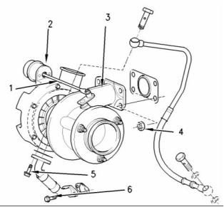
(1) Actuator rod
(2) Actuator
Note: The maximum distortion of the cylinder head
is given in table 3.
(3) Turbocharger
(4) Tighten the nuts to the following torque. .. 47 N·m
(34 lb ft)
(5) Tighten the bolt to the following torque. ..... 9 N·m
(80 lb in)
(6) Tighten the bolt to the following torque. ... 22 N·m
(16 lb ft)
The maximum test pressure for the waste
gate ................................................. 205 kPa (30 psi)
The movement for the rod actuator ................. 1 mm
(0.0394 inch)
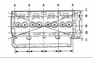
g01006568
Illustration 14
Four Cylinder Engine
Table 3
Maximum Permissible
Table 4
Dimension
Distortion
The part number for
the turbocharger
The pressure for the
waste gate
Width (A)
Length (B)
0.03 mm (0.0018 inch)
0.05 mm (0.0019 inch)
0.05 mm (0.0019 inch)
2674A200
2674A201
2674A202
2674A209
2674A211
2674A215
2674A223
2674A224
2674A225
2674A226
2674A227
100 ± 5 kPa
(14.5040 ± 0.7252 psi)
Diagonal Line (C)
110 ± 5 kPa
(15.9544 ± 0.7252 psi)
i02242611
128 ± 5 kPa
Turbocharger
(18.5651 ± 0.7252 psi)
100 ± 5 kPa
(14.5040 ± 0.7252 psi)
128 ± 5 kPa
(18.5651 ± 0.7252 psi)
128 ± 5 kPa
(18.5651 ± 0.7252 psi)
136 ± 5 kPa
(19.7254 ± 0.7252 psi)
136 ± 5 kPa
(19.7254 ± 0.7252 psi)
136 ± 5 kPa
(19.7254 ± 0.7252 psi)
100 ± 5 kPa
(14.5040 ± 0.7252 psi)
128 ± 5 kPa
(18.5651 ± 0.7252 psi)
g00991357
Illustration 15
Typical turbocharger
This document has been printed from SPI². Not for Resale
![]()
![]()

![]()

SENR9976
11
Specifications Section
i02242613
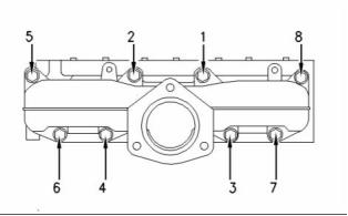
Exhaust Manifold
Four Cylinder Engine
g00976195
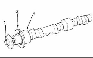
Illustration 18
Typical camshaft
(2) Bolt
Tighten the bolt to the following torque. ... 95 N·m
(70 lb ft)
g00907527
Illustration 16
Tightening sequence
(3) Camshaft thrust washer
Thickness of the thrust washer .. 5.49 to 5.54 mm
(0.216 to 0.218 inch)
Note: The exhaust manifold must be aligned to
the cylinder head. Refer to the Disassembly and
Assembly manual.
Depth of the recess in the cylinder block for the
thrust washer ............................ 5.54 to 5.64 mm
(0.218 to 0.222 inch)
Tighten the exhaust manifold bolts in the sequence
that is shown in illustration 16 to the following
torque. ............................................. 33 N·m (24 lb ft)
Tolerance of the thrust washer in cylinder block
front face ........................... −0.154 to −0.003 mm
(−0.0006 to −0.0001 inch)
i02242614
(4) The diameters of the camshaft journals are given
in the following tables.
Camshaft
Table 5
1104 Diameters of Camshaft Journals
Camshaft Journals
Standard Diameter
50.71 to 50.74 mm
1
(1.9965 to 1.9975 inch)
50.46 to 50.48 mm
2
3
(1.9865 to 1.9875 inch)
49.95 to 49.98 mm
(1.9665 to 1.9675 inch)
Maximum wear on the camshaft journals ... 0.05 mm
(0.0021 inch)
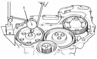
g00987750
Illustration 17
Checking the end play of the camshaft
(1) End play of a new camshaft ..... 0.10 to 0.55 mm
(0.004 to 0.022 inch)
Maximum permissible end play of a worn
camshaft ................................. 0.60 mm (0.023 inch)
This document has been printed from SPI². Not for Resale
![]()
![]()
![]()
![]()

12
SENR9976
Specifications Section
i02242618
Camshaft Bearings
g00629702
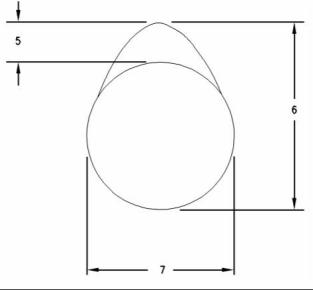
Illustration 19
(5) Camshaft lobe lift
Naturally aspirated
Inlet lobe ............................... 7.382 to 7.482 mm
g00997348
Illustration 20
A typical four cylinder engine
(0.2906 to 0.2946 inch)
Exhaust lobe ......................... 7.404 to 7.504 mm
(0.2914 to 0.2954 inch)
(1) Camshaft bearing
Turbocharged
Inlet lobe ............................... 7.031 to 7.130 mm
The diameter for the installed camshaft
bearing .............................. 50.790 to 50.850 mm
(1.9996 to 2.0020 inch)
(0.2768 to 0.2807 inch)
Exhaust lobe ......................... 7.963 to 8.063 mm
(0.3135 to 0.3174 inch)
i01958095
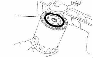
Engine Oil Filter
(6) Camshaft lobe height
(7) Base circle
To determine the lobe lift, use the procedure that
follows:
Spin-on Oil Filter
1. Measure the camshaft lobe height (6).
2. Measure the base circle (7).
3. Subtract the base circle that is found in Step 2
from the camshaft lobe height that is found in Step
1. The difference is the actual camshaft lobe lift.
Maximum permissible clearance between the
actual lobe lift and the specified lobe lift of a new
camshaft ................................. 0.05 mm (0.021 inch)
g00915984
Illustration 21
(1) Seal
This document has been printed from SPI². Not for Resale
![]()
![]()
![]()
![]()
SENR9976
13
Specifications Section
Note: Lubricate the top of the seal with clean engine
oil before installation.
Type ............................................................. Full flow
Pressure to open engine oil filter bypass
valve ............................. 80 to 120 kPa (12 to 18 psi)
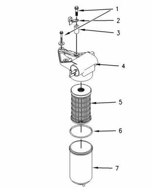
Replaceable Element
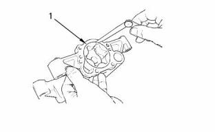
g00989248
Illustration 23
The oil pump for the balancer
g00915985
(1) Clearance of the outer rotor to the
Illustration 22
body .. 0.130 to 0.24 mm (0.0050 to 0.0094 inch)
Note: Lubricate the seal on the oil filter housing with
clean engine oil before installation.
Type ............................................................. Full flow
Pressure to open engine oil filter bypass
valve ........................... 130 to 170 kPa (19 to 25 psi)
(1) Tighten the oil filter housing to the oil filter base
to the following torque. ............. 25 N·m (18 lb ft)
(2) Tighten the drain plug on the oil filter housing to
the following torque. ................... 12 N·m (9 lb ft)
Note: The horizontal filter as a drain plug in the filter
head
(3) Recess for 1/2 inch square drive
i02242623
Engine Oil Pump
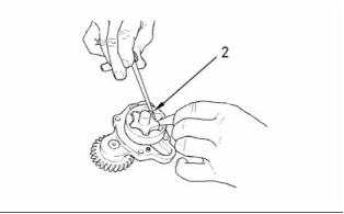
g00989236
Illustration 24
Inner rotor
(2) Clearance of inner rotor to outer
rotor ...................................... 0.050 to 0.200 mm
(0.0020 to 0.0079 inch)
Engines with Balancer Group
Type ............................. Gear-driven differential rotor
Number of lobes
Inner rotor ......................................................... 6
Outer rotor ........................................................ 7
This document has been printed from SPI². Not for Resale
![]()
![]()
![]()
![]()
14
SENR9976
Specifications Section
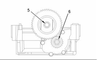
g00989519
Illustration 27
Idler gear and pump gear
Note: Replace the idler gear bolt (5) and the nut for
the oil pump gear (6).
(5) Tighten the idler gear bolt to the following
torque. ...................................... 26 N·m (19 lb ft)
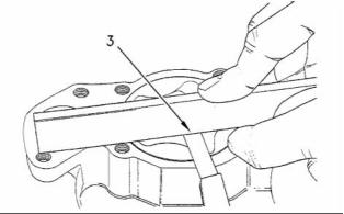
g00989217
Illustration 25
The end play for the rotor
Note: Set the engine to the TC position. Refer to
Testing and Adjusting , “Finding Top Center Position
for No. 1 Piston”. Install the balancer. Refer to the
Disassembly and Assembly manual. Install the gear
for the oil pump and tighten the nut (6).
(3) End play of rotor assembly
Inner rotor .................................. 0.04 to 0.11 mm
(0.0016 to 0.0043 inch)
Outer rotor ................................ 0.04 to 0.00 mm
(0.0016 to 0.0043 inch)
(6) Tighten the nut to the following torque. .... 95 N·m
(70 lb ft)
Tighten the bolts that hold the balancer to the cylinder
block to the following torque. .......... 54 N·m (40 lb ft)
Engines without Balancer Group
Type ............................. Gear-driven differential rotor
Number of lobes
Inner rotor ......................................................... 5
Outer rotor ........................................................ 6
g00938724
Illustration 26
The end cover
(4) Torque for cover bolts for oil pump .......... 26 N·m
(19 lb ft)
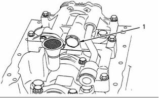
g00938064
Illustration 28
The oil pump
This document has been printed from SPI². Not for Resale
![]()
![]()
![]()
![]()
![]()
![]()
SENR9976
15
Specifications Section
(1) Clearance of the outer rotor to the
body ...................................... 0.152 to 0.330 mm
(0.0059 to 0.0129 inch)
i02242638
Engine Oil Bypass Valve
Installed in the Oil Pump
g00938061
Illustration 29
Checking the clearance
(2) Clearance of inner rotor to outer
rotor ...................................... 0.040 to 0.127 mm
(0.0015 to 0.0050 inch)
g00919893
Illustration 31
Typical engine oil pump
g00938799
Illustration 30
Checking the end play
g00921377
Illustration 32
Relief valve and spring
(3) End play of rotor assembly
(1) Tighten the plug for the relief valve to the
following torque. ....................... 35 N·m (26 lb ft)
Inner rotor ............................. 0.038 to 0.089 mm
(0.0014 to 0.0035 inch)
(2) Plunger
Outer rotor ............................ 0.025 to 0.076 mm
(0.0010 to 0.0029 inch)
Diameter of the plunger ..... 19.186 to 19.211 mm
(0.7554 to 0.7563 inch)
Tighten the bolts that hold the front cover of the oil
pump assembly to the following torque. ........ 26 N·m
(19 lb ft)
Clearance of plunger in bore .. 0.039 to 0.114 mm
(0.0015 to 0.0045 inch)
i01958104
Engine Oil Pressure
The minimum oil pressure at the maximum engine
speed and at normal operating temperature is the
following value. ............................... 300 kPa (43 psi)
This document has been printed from SPI². Not for Resale
![]()
![]()
![]()
![]()
![]()
16
SENR9976
Specifications Section
Installed in the Balancer
i02242687
Engine Oil Pan
Front sealant
g00919890
Illustration 33
Plug
g00990254
Illustration 35
Applying sealant
(1) Apply 1861108 Powerpart silicone rubber
sealant to the cylinder block and to the timing
case.
Note: Apply a sealant bead of 3.5 mm (0.1378 inch)
that is shown in illustration 35.
Rear sealant
g00921379
Illustration 34
The relief valve for the balancer
Note: Install the rear oil seal before sealant is applied
to the bridge.
(1) Tighten the plug for the relief valve to the
following torque. ....................... 35 N·m (26 lb ft)
(2) Plunger
Diameter of the plunger ........ 14.46 to 14.48 mm
(0.5692 to 0.5700 inch)
Clearance of the plunger in the
bore .... 0.04 to 0.08 mm (0.0015 to 0.0031 inch)
g00990255
Illustration 36
Applying sealant
(2) Apply 1861108 Powerpart silicone rubber
sealant to the bridge. The sealant must not
protrude more than 5 mm (0.1969 inch) above
the bridge.
This document has been printed from SPI². Not for Resale
![]()
![]()
![]()
![]()
![]()
SENR9976
17
Specifications Section
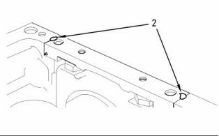
Note: The oil pan must be installed within 10 minutes
The cast iron oil pan
of applying the sealant.
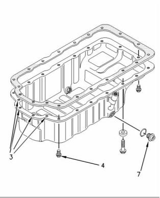
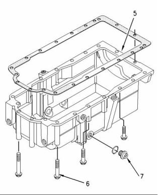
g00990249
Illustration 38
g00990252
Illustration 37
Typical oil pan
The cast iron oil pan
Note: The rear face of the cast iron oil pan (5) must
(3) Tighten the four front bolts to the following
torque. ...................................... 22 N·m (16 lb ft)
be aligned to the rear face of the cylinder block.
(5) The maximum allowed value of the rear face
misalignment. ................. 0.1 mm (0.0039 inch )
(4) Tighten the remaining bolts to the following
torque. ...................................... 22 N·m (16 lb ft)
(6) Bolt
Tighten the front four bolts. Refer to illustration
37. Tighten the remaining bolts and the nuts that
fasten the engine oil pan to the cylinder block to
the following torque. ................. 22 N·m (16 lb ft)
Note: The sealant is applied to new bolts. In order
to reuse the bolts, apply 21820117 Powerpart
threadlock and nutlock to the first three threads of
the used bolts.
Note: The engine may be equipped with an oil drain
plug or the engine may be equipped with a drain
valve.
(7) Drain plug
Tighten the drain plug for the engine oil pan to
the following torque. ...... 34 ± 5 N·m (25 ± 4 lb ft)
This document has been printed from SPI². Not for Resale
![]()
![]()
![]()
18
SENR9976
Specifications Section
(3) Screws
Tighten the screws for the cover plate with a
plastic valve mechanism cover to the following
torque. .................................. 1.3 N·m (11.5 lb in)
Tighten the screws for the cover plate with a
metal valve mechanism cover to the following
torque. ..................................... 1.8 N·m (16 lb in)
(4) Diaphragm
(5) Cap
(6) Spring
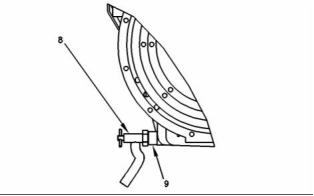
g00990677
Illustration 39
The drain valve
(8) Drain valve
Tighten the drain valve into the adapter to the
following torque. ............ 34 ± 5 N·m (25 ± 4 lb ft)
(9) Adapter
Tighten the adapter into the engine oil pan to the
following torque. ............ 34 ± 5 N·m (25 ± 4 lb ft)
i02242678
Crankcase Breather
g00926200
Illustration 41
(7) O-ring
Note: Apply 21820221 Powerpart red rubber grease
to the O-ring before installing the breather pipe in the
valve mechanism cover.
(8) Tighten the bolts that secure the breather pipe to
the cylinder head to the following torque. .. 9 N·m
(80 lb in)
i01914256
Water Temperature Regulator
and Housing
g00926199
Illustration 40
Tighten the bolts (not shown) that fasten the housing
to the following torque. .................... 22 N·m (16 lb ft)
Breather valve
(1) Plastic cover
(2) Cover plate
This document has been printed from SPI². Not for Resale
![]()
![]()
![]()
![]()
SENR9976
19
Specifications Section
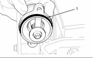
i01904883
Water Pump
g00997234
Illustration 42
O ring
Note: Apply 21820221 Powerpart red rubber grease
to the O-ring (1) in order to install the thermostat
housing.
g00915951
Illustration 44
Tightening sequence
Water Temperature Regulator
Note: Apply 21820117 Powerpart threadlock
nutlock to the first three threads of the bolts before
installation.
Tighten the nine bolts that secure the water pump to
the front housing in the numerical sequence that is
shown to the following torque. ........ 22 N·m (16 lb ft)
Note: Refer to the Disassembly and Assembly
manual in order to service the water pump.
g00906121
Illustration 43
A typical water temperature regulator
Opening temperature ............................ 79 ° to 84 °C
(174 ° to 151 °F)
Full opening temperature ................... 93 °C (199 °F)
Minimum stroke at full open temperature ...... 10 mm
(0.3937 inch)
This document has be, en printed from SPI². Not for Resale
![]()
![]()
![]()
![]()
20
SENR9976
Specifications Section
i02242732
Diameter of the bore in the cylinder
block for the number 3 camshaft
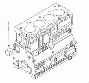
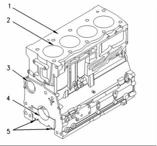
Cylinder Block
journal ............................... 50.038 to 50.089 mm
(1.9700 to 1.9720 inch)
(4) Main bearings for the four cylinder engine
Four Cylinder Engine
Bore in the cylinder block for the main
bearings ............................ 80.416 to 80.442 mm
(3.1660 to 3.1670 inch)
(5) Main bearing cap bolts for the four cylinder
engine
Use the following procedure in order to install the
main bearing cap bolts:
1. Apply clean engine oil to the threads of the main
bearing cap bolts.
2. Put the main bearing caps in the correct position
that is indicated by a number on the top of the
main bearing cap. Install the main bearing caps
with the locating tabs in correct alignment with the
recess in the cylinder block.
3. Evenly tighten the main bearing cap bolts.
Torque for the main bearing cap bolts. .... 245 N·m
(180 lb ft)
g00924764
Illustration 45
Cylinder block
(1) Cylinder block
(2) Cylinder bore ................ 105.000 to 105.025 mm
(4.1338 to 4.1348 inch)
The first oversize bore
diameter .................................. 105.5 to 105.525 mm
(4.1535 to 4.1545 inch)
The second oversize bore
diameter .............................. 106.000 to 106.025 mm
(4.1732 to 4.1742 inch)
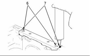
g00938203
The maximum permissible wear for the cylinder bore
................................. 0 to 0.15 mm (0 to 0.0059 inch)
Illustration 46
Use the following procedure in order to install the
Allen head bolts for the bridge.
(3) Camshaft bearings for the four cylinder engine
Diameter of the bore in the cylinder
block for the number 1 camshaft
bearing .............................. 55.563 to 55.593 mm
(2.1875 to 2.1887 inch)
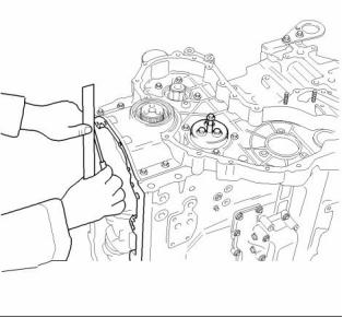
Note: Install the rear seal before sealant is applied.
1. Use a straight edge in order to ensure that the
bridge is aligned with the rear face of the cylinder
block.
Diameter of the bore in the cylinder
block for the number 2 camshaft
journal ............................... 50.546 to 50.597 mm
(1.9900 to 1.9920 inch)
2. Tighten the Allen head bolts (6) for the bridge.
Torque for the Allen head bolts .. 16 N·m (12 lb ft)
This document has been printed from SPI². Not for Resale
![]()
![]()
![]()
SENR9976
21
Specifications Section
3. When the bridge is installed on the cylinder block,
apply 21826038 POWERPART Silicon Adhesive
into groove (7) at each end of the bridge. Apply the
sealant into the groove until the sealant is forced
through the bottom end of the groove in the bridge.
Note: The timing mark is toward the outside of
the crankshaft when the gear is installed on the
crankshaft.
Note: All new turbocharged engines and
turbocharged aftercooled engines have crankshafts
that are nitrocarburised. The crankshaft can also
be nitrided for 20 hours, if the nitrocarburised
process is not available. After a crankshaft has
been machined, the crankshaft must be rehardened.
Inspect the crankshaft for cracks before machining
and after machining. Naturally aspirated engines
have induction hardened crankshafts.
Total height of the cylinder block between the top and
the bottom faces. ................ 441.173 to 441.274 mm
(17.3689 to 17.3729 inch)
i02242736
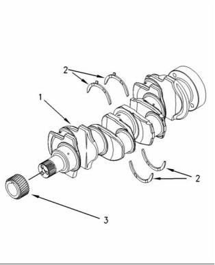
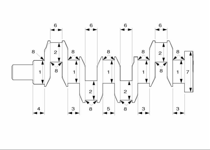
Crankshaft
g00992214
Illustration 47
The crankshaft for the four cylinder engine
(1) Crankshaft for the four cylinder engine
The maximum end play of the crankshaft ... 0.51 mm
(0.0201 inch)
(2) Thrust washers
Standard thickness ................... 2.26 to 2.31 mm
(0.089 to 0.091 inch)
Oversize thickness ................... 2.45 to 2.50 mm
(0.097 to 0.098 inch)
(3) The crankshaft gear
Maximum permissible temperature of the gear for
installation on the crankshaft ........... 180 °C (356 °F)
This document has been printed from SPI². Not for Resale
![]()
![]()
22
SENR9976
Specifications Section
g01017233
Illustration 48
The 1104 engine crankshaft
Note: Refer to illustration 48 in order to use table 6.
The four cylinder engine.
This document has been printed from SPI². Not for Resale
![]()
![]()
SENR9976
23
Specifications Section
Table 6
The undersize diameter of the Crankshaft Journals
NUMBER
0.25 mm (0.010 inch)
0.51 mm (0.020 inch)
0.76 mm (0.030 inch)
75.909 mm (2.9885 inch) to
75.930 mm (2.9894 inch)
75.649 mm (2.9783 inch) to
75.670 mm (2.9791 inch)
75.399 mm (2.9685 inch) to
75.420 mm (2.9693 inch)
1
2
3
4
5
63.220 mm (2.4890 inch) to
63.240 mm (2.4898 inch)
62.960 mm (2.4787 inch) to
62.982 mm (2.4796 inch)
62.708 mm (2.4688 inch) to
62.728 mm (2.4696 inch)
39.47 mm
N/A
N/A
N/A
N/A
N/A
N/A
(1.5539 inch)maximum
37.44 mm
(1.4740 inch)maximum
44.68 mm
(1.7591 inch)maximum
40.55 mm
6
7
8
N/A
N/A
N/A
N/A
N/A
N/A
(1.5965 inch)maximum
Do not machine this diameter.
3.68 mm (0.1449 inch) to
3.96 mm (0.1559 inch)
Refer to table 7 for the maximum run out of the
crankshaft journals.
i01958114
Crankshaft Seals
The maximum difference in value between one
crankshaft journal and the next crankshaft journal
............................................... 0.10 mm (0.0039 inch)
Table 7
Journal
(1)
Excessive run out
Mounting
(2)
0.08 mm (0.0031 inch)
0.15 mm (0.0059 inch)
0.08 mm (0.0031 inch)
Mounting
(3)
(4)
(5)
Refer to the Specifications Module, “Connecting Rod
Bearing Journal” topic for more information on the
connecting rod bearing journals and connecting rod
bearings.
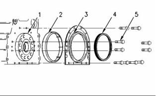
g00915078
Illustration 49
(1) Crankshaft
(2) Plastic sleeve
(3) Crankshaft seal
(4) Alignment tool
Refer to the Specifications Module, “Main Bearing
Journal” topic for information on the main bearing
journals and for information on the main bearings.
This document has been printed from SPI². Not for Resale
![]()


![]()
24
SENR9976
Specifications Section
i01958141
Main Bearing Journal
Refer to the Specifications module, “Crankshaft”
topic for information on the undersize main bearing
journals, and information on the width of main bearing
journals.
The original size of the main bearing
journal ..................................... 76.159 to 76.180 mm
(2.9984 to 2.9992 inch)
Maximum permissible wear of the main bearing
journals ............................... 0.040 mm (0.0016 inch)
Radius of the fillet of the main bearing
journals ..... 3.68 to 3.69 mm (0.1448 to 0.1452 inch)
Surface finish of bearing journals, crank pins and
radii ................................... 0.4 microns (16 µ inches)
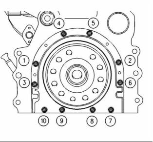
g00915076
Illustration 50
(5) Tighten bolts 1, 2, 3, 4, 5, 6, 7, and 10 in the
sequence that is shown in Illustration 50 to the
following torque. ....................... 22 N·m (16 lb ft)
The shell for the main bearings
The shells for the main bearings are available
for remachined journals which have the following
undersize dimensions.
Remove the alignment tool.
Tighten bolts 8 and 9 in the sequence that is shown
in Illustration 50 to the following torque. ........ 22 N·m
(16 lb ft)
Undersize bearing shell .... 0.25 mm (0.010 inch)
Undersize bearing shell .... 0.51 mm (0.020 inch)
Undersize bearing shell .... 0.75 mm (0.030 inch)
i01958137
Connecting Rod Bearing
Journal
Thickness at center of the shells .. 2.083 to 2.089 mm
(0.0820 to 0.0823 inch)
Width of the main bearing shells .. 31.62 to 31.88 mm
(1.244 to 1.255 inch)
Clearance between the bearing shell and the main
bearing journals ........................... 0.057 to 0.117 mm
(0.0022 to 0.0046 inch)
Refer to the Specifications Module, “Crankshaft” topic
for information on the undersize crankshaft journals.
The original size of the connecting rod bearing
journal ... 63.47 to 63.49 mm (2.4988 to 2.4996 inch)
Maximum permissible wear of the connecting rod
bearing journals .................... 0.04 mm (0.0016 inch)
Width of the connecting rod bearing
journals ..... 40.35 to 40.42 mm (1.589 to 1.591 inch)
Radius of the fillet of the connecting rod bearing
journals ......... 3.68 to 3.96 mm (0.145 to 0.156 inch)
Surface finish of connecting rod bearing journals and
radii ................................. Ra 0.4 microns (16 µ inch)
This document has been printed from SPI². Not for Resale
![]()
![]()
SENR9976
25
Specifications Section
i01958156
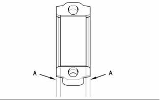
Connecting Rod
g00995584
Illustration 52
Alignment of the bearing shell
Note: The bearing shell for the connecting rod
must be aligned equally from both ends of the
connecting rod. Refer to (A) in figure 52. Refer to the
Disassembly and assembly manual for information
on the alignment tool.
Table 8
Bearing Width for the
Connecting Rod
31.62 to 31.88 mm
(1.245 to 1.255 inch)
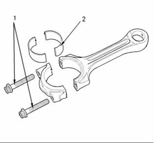
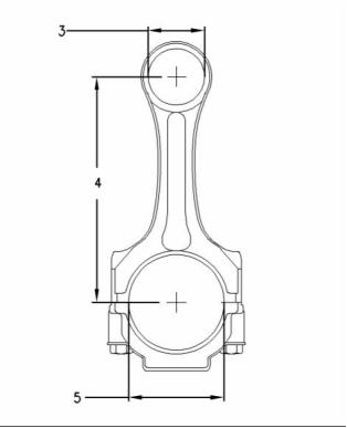
g00907738
Illustration 51
Bearing Width for the
Connecting Rod Cap
31.55 to 31.88 mm
The mating surfaces of the connecting rod are
produced by hydraulically fracturing the forged
connecting rod.
(1.2405 to 1.255 inch)
Thickness of Connecting
Rod Bearing at the
Center
1.835 to 1.842 mm
(0.0723 to 0.0725 inch)
(1) Tighten the torx screws for the connecting rod to
the following torque. ................. 18 N·m (13 lb ft)
Thickness of Connecting
Rod Bearing for the Cap
at the Center
1.835 to 1.842 mm
(0.0722 to 0.0725 inch)
Tighten the torx screws for the connecting rod again
to the following torque. .................... 70 N·m (52 lb ft)
0.030 to 0.081 mm
Bearing Clearance
(0.0012 to 0.0032 inch)
Tighten the torx screws for the connecting rod for
an additional 120 degrees. The torx screws for
the connecting rod (1) must be replaced after this
procedure.
Table 9
Undersized Connecting Rod Bearing
Note: Always tighten the connecting rod cap to the
connecting rod, when the assembly is out of the
engine. Tighten the assembly to the following torque
20 N·m (14 lb ft).
0.25 mm (0.010 inch)
0.51 mm (0.020 inch)
0.76 mm (0.030 inch)
(2) The bearing shell for the connecting rod
This document has been printed from SPI². Not for Resale
![]()
![]()
![]()


26
SENR9976
Specifications Section
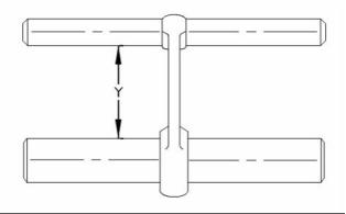
Table 10
Length Grades for Connecting Rods
Grade Letter Color Code Length (Y)
165.728 to 165.761 mm
(6.5247 to 6.5260 inch)
F
G
H
J
Red
Orange
White
Green
Purple
Blue
165.682 to 165.715 mm
(6.5229 to 6.5242 inch)
165.637 to 165.670 mm
(6.5211 to 6.5224 inch)
165.591 to 165.624 mm
(6.5193 to 6.5206 inch)
165.545 to 165.578 mm
(6.5175 to 6.5188 inch)
K
L
165.499 to 165.532 mm
(6.5157 to 6.4961 inch)
i01958185
Piston and Rings
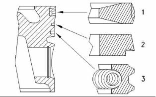
g00907744
Illustration 53
(3) Diameter of the parent bore for the piston
pin ....... 43.01 to 43.04 mm (1.693 to 1.694 inch)
(4) Distance between the parent bores
........ 219.05 to 219.10 mm (8.624 to 8.626 inch)
(5) Diameter for the parent bore for the connecting
rod bearing ........................... 67.21 to 67.22 mm
(2.6460 to 2.6465 inch)
g00888215
Illustration 55
A typical example of a piston and rings
(1) Top compression ring
Naturally Aspirated
The shape of the top compression
ring ...................... Rectangular with a barrel face
Width of the top compression
ring ........ 2.475 to 2.49 mm (0.097 to 0.098 inch)
Clearance between the top compression ring and
the piston groove ........................ 0.09 to .15 mm
(0.0035 to 0.0059 inch)
g00915056
Illustration 54
Ring gap ................................... 0.30 to 0.55 mm
(0.0118 to 0.0216 inch)
Connecting rods are color coded. The color code
is a reference for the length (Y) of the connecting
rod. Refer to table 10 for the different lengths of
connecting rods.
This document has been printed from SPI². Not for Resale
![]()
![]()
![]()

![]()
SENR9976
27
Specifications Section
Turbocharged
The combustion bowl re-entrant angle for the
turbocharged engine ............................... 80 degrees
The shape of the top compression
ring ........................... Keystone with a barrel face
The combustion bowl re-entrant angle for the
Width of the top compression ring .......... tapered
naturally aspirated engine ....................... 70 degrees
Ring gap ................................... 0.30 to 0.55 mm
(0.0118 to 0.0216 inch)
Piston height above cylinder block .. 0.21 to 0.35 mm
(0.008 to 0.014 inch)
Note: When you install a new top compression ring,
make sure that the word “TOP” is facing the top of the
piston. New top piston rings have a red identification
mark which must be on the left of the ring end gap
when the top piston ring is installed on an upright
piston.
Width of top groove in piston for the naturally
aspirated engine ............................. 2.58 to 2.60 mm
(0.1016 to 0.1024 inch)
Width of top groove in piston for the turbocharged
engine .......................................................... Tapered
(2) Intermediate compression ring
Width of second groove in piston .... 2.54 to 2.56 mm
(0.1000 to 0.1008 inch)
The shape of the intermediate compression
ring ......................................... Internal step in the
bottom edge with a tapered face
Width of third groove in piston ........ 3.52 to 3.54 mm
(0.1386 to 0.1394 inch)
Width of intermediate compression
Piston pin
ring .......... 2.47 to 2.49 mm (0.097 to 0.098 inch)
Diameter of a new piston
Clearance between the intermediate compression
ring and the piston groove ........ 0.05 to 0.09 mm
(0.002 to 0.003 inch)
pin ..................................... 39.694 to 39.700 mm
(1.5628 to 1.5630 inch)
Diameter of the bore for the piston
pin ..................................... 39.703 to 39.709 mm
(1.5631 to 1.5633 inch)
Ring gap ................................... 0.70 to 0.95 mm
(0.0275 to 0.0374 inch)
Note: When you install a new intermediate
compression ring, make sure that the word “TOP” is
facing the top of the piston. New intermediate rings
have a green identification mark which must be on
the left of the ring end gap when the top piston ring is
installed on an upright piston.
i02242750
Piston Cooling Jet
(3) Oil control ring
Shape of oil control
ring ............... two-piece coil that is spring loaded
Width of oil control ring ............. 3.47 to 3.49 mm
(0.1366 to 0.1374 inch)
Clearance between the oil control ring and the
groove in the piston .................. 0.03 to 0.07 mm
(0.0011 to 0.0027 inch)
Ring gap ................................... 0.30 to 0.55 mm
(0.0118 to 0.0216 inch)
Note: A pin is used in order to hold both ends of the
spring of the oil control ring in position. The ends of
the spring of the oil control ring must be installed
opposite the end gap of the oil control ring.
g00942652
Illustration 56
(1) Installed piston cooling jets
The spring loaded valve must move freely. Tighten
the bolt to the following torque. ........... 9 N·m (7 lb ft)
Note: Ensure that the ring end gaps of the piston
rings are spaced 120 degrees from each other.
Piston
Note: An arrow which is marked on the piston crown
must be toward the front of the engine.
This document has been printed from SPI². Not for Resale
![]()
![]()
28
SENR9976
Specifications Section
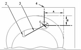
Piston Cooling Jet Alignment
g01006929
Illustration 57
(2) Piston cooling jet
(3) Rod
(4) Cylinder block
Use the following procedure in order to check the
alignment of the piston cooling jet.
g00995663
Illustration 58
Alignment
1. Insert rod (3) into the end of the piston cooling
jet (2). Rod (3) has a diameter of 1.70 mm
(0.067 inch). Rod (3) must protrude out of the top
of the cylinder block.
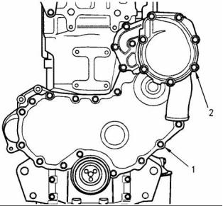
(1) Tighten the bolts that fasten the front cover to the
front housing to the following torque. ....... 22 N·m
(16 lb ft)
2. Dimension (A) is 55.25 mm (2.1752 inch) and
dimension (B) is 14 mm (0.5512 inch). Dimension
(A) and dimension (B) are tangent to the cylinder
bore (4).
3. The position of the rod (3) must be within
dimension (C). Dimension (C) is 14 mm
(0.5512 inch).
i01957083
Front Housing and Covers
The front housing must be aligned to the cylinder
block face. ......................... + 0.05 to minus 0.05 mm
(+ 0.0020 to minus 0.0020 inch )
g00918672
Illustration 59
Front cover
(2) Tighten the bolts that fasten the water pump to the
front housing to the following torque. ....... 22 N·m
(16 lb ft)
Note: Refer to Specifications, “Water Pump” for the
correct bolt tightening sequence for the water pump.
This document has been printed from SPI². Not for Resale
![]()
![]()
![]()
![]()
SENR9976
29
Specifications Section
i01794692
Bore diameter of the idler gear
.............................................. 57.14 to 57.18 mm
(2.2495 to 2.2512 inch)
Gear Group (Front)
Bore diameter of idler gear with roller
bearings ................................ 72.35 to 72.36 mm
(2.8484 to 2.8488 inch)
Width of idler gear and split bearing
assembly .............................. 30.14 to 30.16 mm
(1.186 to 1.187 inch)
Inside diameter of idler gear bearings with
flanges .................................. 50.78 to 50.80 mm
(1.999 to 2.000 inch)
Outside diameter of idler gear
hub .. 50.70 to 50.74 mm (1.9961 to 1.9976 inch)
Outside diameter of idler gear hub with roller
bearings ............................ 49.975 to 49.988 mm
(1.9675 to 1.9680 inch)
Clearance of idler gear bearing on
hub ...... 0.04 to 0.10 mm (0.0016 to 0.0039 inch)
Idler gear end play .................... 0.10 to 0.20 mm
(0.004 to 0.008 inch)
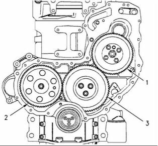
g00918708
Idler gear end play with roller
Illustration 60
bearings .................................... 0.10 to 0.75 mm
(0.0039 to 0.0295 inch)
(1) Fuel injection pump drive gear
Tighten the bolts for the fuel injection pump drive
gear to the following torque. ..... 22 N·m (16 lb ft)
Maximum permissible end play ............ 0.38 mm
(0.015 inch)
Bore diameter of the fuel injection pump drive
gear ................................. 29.995 to 30.021 mm
(1.1809 to 1.1819 inch)
Number of teeth .............................................. 73
Clearance between the fuel injection pump drive
gear and the drive gear hub .. 0.005 to 0.141 mm
(0.0002 to 0.0060 inch)
Number of teeth .............................................. 68
(2) Camshaft gear
Tighten the bolt for the camshaft gear to the
following torque. ....................... 95 N·m (70 lb ft)
Bore diameter of the camshaft
gear ...................................... 34.93 to 34.95 mm
(1.3750 to 1.3760 inch)
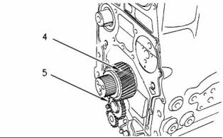
g00918756
Illustration 61
Outside diameter of camshaft
(4) Crankshaft gear
hub .. 34.90 to 34.92 mm (1.3741 to 1.3747 inch)
Bore diameter of crankshaft gear
.......................................... 47.625 to 47.650 mm
(1.8750 to 1.8760 inch)
Clearance between camshaft gear and camshaft
hub .. 0.003 to 0.048 mm (0.0001 to 0.0019 inch)
Number of teeth .............................................. 68
(3) Idler gear and hub
Outside diameter of crankshaft
hub .................................... 47.625 to 47.645 mm
(1.8750 to 1.8758 inch)
Tighten the bolts for the idler gear to the following
torque. ...................................... 44 N·m (33 lb ft)
Clearance of gear on
crankshaft ......................... −0.020 to +0.020 mm
(−0.0008 to +0.0008 inch)
This document has been printed from SPI². Not for Resale
![]()
![]()
![]()
30
SENR9976
Specifications Section
Number of teeth .............................................. 34
(5) Idler gear
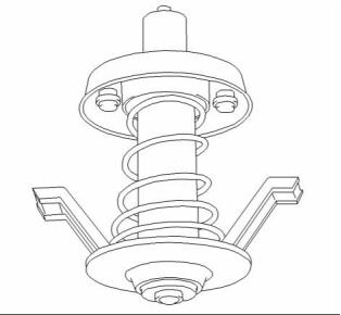
i02253807
Flywheel
Engines with balancer group
Inside bore diameter of idler
gear .................................. 37.197 to 37.212 mm
(1.5431 to 1.5437 inch)
Outside diameter of idler gear
hub .................................... 37.152 to 37.162 mm
(1.4626 to 1.4630 inch)
End play of the oil pump idler
gear ...................................... 0.120 to 0.270 mm
(0.0047 to 0.0108 inch)
Engines without the balancer group
Inside diameter of oil pump idler gear
bearing .............................. 16.012 to 16.038 mm
(0.6303 to 0.6314 inch)
Outside diameter of oil pump idler gear
shaft .................................. 15.966 to 15.984 mm
(0.6285 to 0.6292 inch)
Clearance of oil pump idler gear bearing on
shaft ...................................... 0.028 to 0.072 mm
(0.0011 to 0.0028 inch)
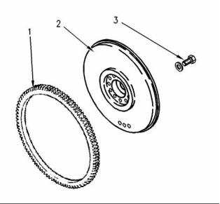
g00584712
Illustration 62
Standard flywheel
End play of the oil pump idler
gear ...................................... 0.050 to 0.275 mm
(0.0019 to 0.0108 inch)
(1) Flywheel ring gear
Backlash values
Heat the flywheel ring gear to the following
temperature. .............................. 250 °C (480 °F)
Backlash between drive gear and idler gear of
balancer (if equipped) ........... 0.097 to 0.170 mm
(0.0038 to 0.0066 inch)
Note: Do not use an oxyacetylene torch to heat the
flywheel ring gear.
Backlash between idler gear and oil pump drive
gear ...................................... 0.046 to 0.106 mm
(0.0018 to 0.0041 inch)
(2) Flywheel
(3) Bolt
Backlash between oil pump idler gear and
crankshaft gear ..................... 0.095 to 0.160 mm
(0.0037 to 0.0063 inch)
Tighten the flywheel bolts to the following
torque. .................................... 105 N·m (77 lb ft)
Backlash between the idler gear and the
crankshaft gear ..................... 0.064 to 0.124 mm
(0.0025 to 0.0049 inch)
Backlash between camshaft gear and idler
gear ...................................... 0.052 to 0.107 mm
(0.0020 to 0.0042 inch)
Backlash between fuel injection pump gear and
idler gear ............................... 0.054 to 0.109 mm
(0.0021 to 0.0043 inch)
Backlash between water pump gear and fuel
injection pump gear .............. 0.073 to 0.133 mm
(0.0028 to 0.0052 inch)
This document has been printed from SPI². Not for Resale
![]()
![]()
SENR9976
31
Specifications Section
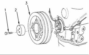
i02243052
Note: Recheck the torque of the bolts (1) twice.
(2) Thrust block
Flywheel Housing
(3) Crankshaft pulley
Four cylinder
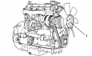
i01958344
Fan Drive
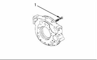
g00631781
Illustration 63
(1) Bolt
Tighten the bolts for the cast iron flywheel
housing to the following torque:
M10 “8.8” .................................. 44 N·m (33 lb ft)
M10 “10.9” ................................ 63 N·m (47 lb ft)
M12 “8.8” .................................. 75 N·m (55 lb ft)
M12 “10.9” ............................... 115 N·m (85 lb ft)
g00926178
Illustration 65
A typical fan drive
(1) Tighten the bolts for the fan to the following
torque. ...................................... 22 N·m (16 lb ft)
Tighten the bolts that secure the fan drive pulley to
the hub to the following torque (not shown). .. 22 N·m
(16 lb ft)
i02253806
Crankshaft Pulley
Fan drive housing
Tighten the bolts that secure the fan drive housing
to the cylinder head to the following torque (not
shown). ........................................... 44 N·m (32 lb ft)
Bearing bore for the housing .. 61.986 to 62.005 mm
(2.4404 to 2.4411 inch)
Outer bearing diameter ........... 61.987 to 62.000 mm
(2.4404 to 2.4409 inch)
Interference fit for the
bearing .............................. 0.014 to minus 0.018 mm
(0.0006 to minus 0.0007 inch)
The outer diameter of the
g00915497
Illustration 64
A standard pulley
shaft ... 25.002 to 25.011 mm (0.9843 to 0.9847 inch)
Maximum permissible end play of the shaft .. 0.20 mm
(0.0079 inch)
Note: Lubricate the threads of the bolts with clean
engine oil before installation.
(1) Tighten the three bolts for the crankshaft pulley
to the following torque. ............ 115 N·m (85 lb ft)
This document has been printed from SPI². Not for Resale
![]()
![]()
![]()
![]()
32
SENR9976
Specifications Section
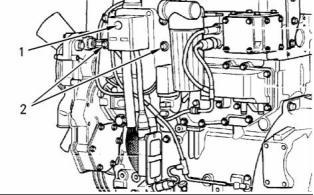
i01721280
Polarity ............................................... Negative earth
Engine Lifting Bracket
V-Belt
Note: The V-belt must be checked by a gauge. Refer
to the Testing and Adjusting, “V-Belt-Test” for the
correct type of gauge in order to check the V-belt.
All engines are equipped with two engine lifting
brackets.
Tighten the two bolts on each engine lifting
V-belt tension ..................................... 535 N (120 lb)
bracket to the following torque. .. 44 N·m (32 lb ft)
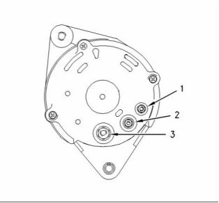
i01958367
Alternator
12 Volt and 24 Volt Alternator
g00959541
Illustration 66
A typical alternator
(1) Tighten terminal nut “W” to the following
torque. ........................................ 2 N·m (17 lb in)
(2) Tighten terminal nut “D+” to the following
torque. ..................................... 4.3 N·m (38 lb in)
(3) Tighten terminal nut “B+” to the following
torque. ..................................... 4.3 N·m (38 lb in)
Tighten the pulley nut (not shown) to the following
torque. ............................................. 80 N·m (59 lb ft)
Alignment of the alternator pulley to the crankshaft
pulley .............................. ± 2.4 mm ( ± 0.0945 inch)
Rotation .................................................... clockwise
This document has been printed from SPI². Not for Resale
![]()
![]()
SENR9976
33
Specifications Section
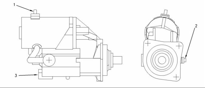
i01958653
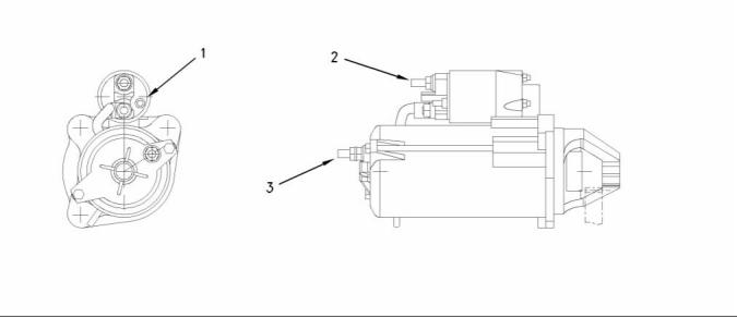
Starter Motor
24 Volt Starter Motor
g00974968
Illustration 67
The 24 volt starter motor which shows the electrical connections
(1) Tighten the negative terminal nut to the following
torque. ....................................... 15 N·m (11 lb ft)
(2) Tighten the positive terminal nut to the following
torque. ...................................... 21 N·m (15 lb ft)
(3) Tighten the solenoid terminal to the following
torque. ..................................... 3.5 N·m (31 lb in)
Rated voltage ................................................ 24 volts
Pull in voltage ............................................... 16 volts
This document has been printed from SPI². Not for Resale
![]()
![]()
34
SENR9976
Specifications Section
12 Volt Starter Motor
g00977365
Illustration 68
The 12 volt starter motor which shows the electrical connections
(1) Tighten the solenoid terminal to the following
torque. ....................................... 8 N·m ( 70 lb in)
(2) Tighten the positive terminal nut to the following
torque. ....................................... 6 N·m ( 53 lb in)
(3) Tighten the negative terminal nut to the following
torque. ....................................... 8 N·m (70 lb in)
Rated voltage ................................................ 12 volts
Pull in voltage ................................................. 8 volts
i02245817
g00884683
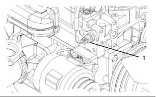
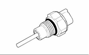
Coolant Temperature Sensor
Illustration 70
(1) Tighten the coolant temperature sensor to the
following torque. ....................... 20 N·m (15 lb ft)
g01131749
Illustration 69
Location of the coolant temperature sensor
This document has been printed from SPI². Not for Resale
![]()
![]()
![]()
![]()
SENR9976
35
Specifications Section
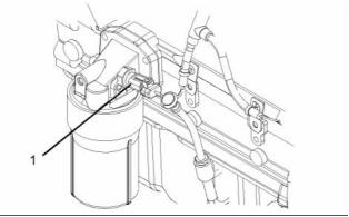
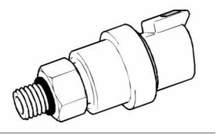
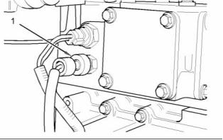
i02245818
Engine Oil Pressure Sensor
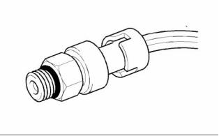
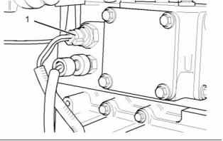
i02245819
Boost Pressure Sensor
g01131721
Illustration 71
g01130928
Illustration 73
Location of the engine oil pressure sensor
Location of the boost pressure sensor
g00884723
Illustration 72
g00884730
Illustration 74
(1) Tighten the engine oil pressure sensor to the
following torque. ......................... 10 N·m (7 lb ft)
(1) Tighten the boost pressure sensor to the following
torque. ........................................ 10 N·m (7 lb ft)
This document has been printed from SPI². Not for Resale
![]()
![]()
![]()
![]()
![]()
36
SENR9976
Specifications Section
i02245820
Inlet Manifold Temperature
i02245821
Speed/Timing Sensor
Sensor
g01131722
Illustration 77
Location of the speed/timing sensor
g01131036
Illustration 75
Location of the inlet manifold temperature sensor
g00884736
Illustration 78
g00884683
Illustration 76
(1) Tighten the bolt for the speed/timing sensor to
the following torque. ................. 22 N·m (16 lb ft)
(1) Tighten the inlet manifold temperature sensor to
the following torque. ................. 20 N·m (15 lb ft)
This document has been printed from SPI². Not for Resale
![]()
![]()
![]()

![]()
![]()
SENR9976
37
Specifications Section
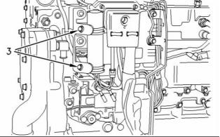
i02245822
i02253813
Voltage Load Protection
Module
Glow Plugs
g00955714
Illustration 81
g00915868
Typical example
Illustration 79
(1) Tighten the glow plugs (3) in the cylinder head to
the following torque. .................. 15 N·m (11 lb ft)
(3) Tighten the bolts for the clips that hold the VLPM
to the following torque. ............. 22 N·m (16 lb ft)
Tighten the nuts (2) for the bus bar (1) that is
installed on top of the glow plugs to the following
torque. ............................................... 2 N·m (18 lb in)
i02246071
Electronic Control Module
Voltage ................................................. 12 or 24 volts
g00915338
Illustration 80
(1) Tighten the allen head screw that secures the
harness connector to the ECM to the following
torque. ..................................... 2.3 N·m (20 lb in)
(2) Tighten the bolts that hold the ECM to the engine
to the following torque. ............. 22 N·m (16 lb ft)
This document has been printed from SPI². Not for Resale
![]()
![]()
![]()
![]()
38
SENR9976
Index Section
Index
A
Flywheel ................................................................ 30
Flywheel Housing .................................................. 31
Four cylinder...................................................... 31
Front Housing and Covers..................................... 28
Fuel Injection Lines................................................ 4
Fuel Injection Pump............................................... 4
Bosch VP30 ....................................................... 4
Fuel Injectors......................................................... 5
Fuel Transfer Pump............................................... 6
Alternator............................................................... 32
12 Volt and 24 Volt Alternator ............................ 32
V-Belt ................................................................. 32
B
Boost Pressure Sensor.......................................... 35
G
C
Gear Group (Front)................................................ 29
Glow Plugs ............................................................ 37
Camshaft............................................................... 11
Camshaft Bearings................................................ 12
Connecting Rod..................................................... 25
Connecting Rod Bearing Journal........................... 24
Coolant Temperature Sensor................................. 34
Crankcase Breather............................................... 18
Crankshaft ............................................................ 21
Crankshaft Pulley .................................................. 31
Crankshaft Seals................................................... 23
Cylinder Block........................................................ 20
Four Cylinder Engine ......................................... 20
Cylinder Head........................................................ 9
Cylinder Head Valves ............................................ 7
I
Important Safety Information................................. 2
Inlet Manifold Temperature Sensor........................ 36
L
Lifter Group............................................................ 6
M
E
Main Bearing Journal............................................. 24
The shell for the main bearings.......................... 24
Electronic Control Module ..................................... 37
Engine Design....................................................... 4
Four Cylinder Engine ......................................... 4
Engine Lifting Bracket............................................ 32
Engine Oil Bypass Valve ....................................... 15
Installed in the Balancer..................................... 16
Installed in the Oil Pump.................................... 15
Engine Oil Filter..................................................... 12
Replaceable Element......................................... 13
Spin-on Oil Filter ................................................ 12
Engine Oil Pan....................................................... 16
Front sealant...................................................... 16
Rear sealant....................................................... 16
The cast iron oil pan........................................... 17
Engine Oil Pressure............................................... 15
Engine Oil Pressure Sensor.................................. 35
Engine Oil Pump.................................................... 13
Engines with Balancer Group ............................ 13
Engines without Balancer Group ....................... 14
Exhaust Manifold................................................... 11
Four Cylinder Engine ......................................... 11
P
Piston and Rings ................................................... 26
Piston................................................................. 27
Piston Cooling Jet.................................................. 27
Piston Cooling Jet Alignment............................. 28
R
Rocker Shaft.......................................................... 6
S
Specifications Section ........................................... 4
Speed/Timing Sensor............................................ 36
Starter Motor.......................................................... 33
12 Volt Starter Motor.......................................... 34
24 Volt Starter Motor........., ................................. 33
F
Fan Drive............................................................... 31
Fan drive housing .............................................. 31
This document has been printed from SPI². Not for Resale
![]()
SENR9976
39
Index Section
T
Table of Contents................................................... 3
Turbocharger......................................................... 10
Four Cylinder Engine ......................................... 10
V
Valve Mechanism Cover........................................ 7
Voltage Load Protection Module............................ 37
W
Water Pump........................................................... 19
Water Temperature Regulator and Housing.......... 18
Water Temperature Regulator............................ 19
This document has been printed from SPI². Not for Resale
免費(fèi)熱線(xiàn)
400-100-8969???15088860848
400-100-8969???15088860848
機(jī)組銷(xiāo)售
0574-26871589? 15267810868
0574-26871589? 15267810868
配件銷(xiāo)售
0574-26886646? 15706865167
0574-26886646? 15706865167
維修熱線(xiàn)
0574-26871569 18658287286
0574-26871569 18658287286
手機(jī)端

微信公眾號(hào)
在線(xiàn)客服