 English
 Espaol
 Franais
 阿拉伯
阿拉伯 中文(簡)
中文(簡) Deutsch
 Italiano
 Português
 日本
日本 韓國
韓國 български
 hrvatski
 esky
esky Dansk
Dansk Nederlands
 suomi
suomi Ελληνικ
 印度
印度 norsk
norsk Polski
 Roman
Roman русский
 Svenska
 珀金斯Perkins1600操作保養(yǎng),珀金斯Perkins1600操作保養(yǎng)技術(shù)支持中心,珀金斯Perkins1600操作保養(yǎng)代理商,珀金斯Perkins1600操作保養(yǎng)銷售服務(wù)中心,珀金斯Perkins1600操作保養(yǎng)價格規(guī)格資料查詢,寧波日昕動力科技有限公司

首頁
產(chǎn)品展示>珀金斯Perkins1600操作保養(yǎng)
珀金斯Perkins1600操作保養(yǎng)
詳細(xì)描述
Operation and
Maintenance
Manual
1600 Series Industrial Engine
XGA (Engine)
XGB (Engine)
XGD (Engine)
XGE (Engine)
XGF (Engine)
XGH (Engine)
This document is printed from SPI². Not for RESALE
![]()
![]()
![]()
![]()
Important Safety Information
Most accidents tha t involve produc t op eration, ma intena nc e and repair are caus ed by failure to
ob serve basic safety rules or precautions . An accident can often be avoided by recog nizing pote ntially
ha za rdous situations before an accident oc curs . A person mus t be alert to pote ntial ha za rds. This
person should also ha ve the ne cessary training, skills and tools to perform the se func tions properly.
Improper operation, lubrication, maintenance or repair of this product can be dangerous and
could result in injury or death.
Do not operate or perform any lubrication, maintenance or repair on this product, until you have
read and understood the operation, lubrication, maintenance and repair information.
Sa fety precautions and warning s are provided in this ma nua l and on the produc t. If the se ha za rd
warning s are not he eded, bod ily injury or death could oc cur to you or to othe r persons .
The ha za rds are identified by the “Safety Alert Symb ol” and followed by a “Signa l Word” suc h as
“DANGER”, “WARNING” or “CAUTION”. The Sa fety Alert “WARNING” label is shown below.
The me aning of this safety alert symb ol is as follows:
Attention! Become Alert! Your Safety is Involved.
The me ssage tha t appears und er the warning explains the ha za rd and can be either written or
pictorially presente d.
Op erations tha t ma y caus e produc t dama ge are identified by “NOTICE” labels on the produc t and in
this pub lication.
Perkins cannot anticipate every possible circumstance that might involve a potential hazard. The
warnings in this publication and on the product are, therefore, not all inclusive. If a tool, procedure,
work method or operating technique that is not specifically recommended by Perkins is used,
you must satisfy yourself that it is safe for you and for others. You should also ensure that the
product will not be damaged or be made unsafe by the operation, lubrication, maintenance or
repair procedures that you choose.
The informa tion, specifications , and illustrations in this pub lication are on the basis of informa tion tha t
was available at the time tha t the pub lication was written. The specifications , torque s, pressure s,
me asure me nts , adjustme nts , illustrations , and othe r items can cha ng e at any time. These cha ng es can
affect the service tha t is given to the produc t. Ob tain the comp lete and mos t current informa tion before
you start any job. Pe rkins dealers or Pe rkins distributors ha ve the mos t current informa tion available.
When replacement parts are required for this
product Perkins recommends using Perkins
replacement parts.
Failure to heed this warning can lead to prema-
ture failures, product damage, personal injury or
death.
This document is printed from SPI². Not for RESALE
![]()
![]()
SEBU8455
3
Table of Contents
Table of Contents
Warranty Section
Warranty Information ............................................ 86
Foreword ................................................................. 4
Index Section
Safety Section
Index ..................................................................... 87
Safety Messages .................................................... 5
General Hazard Information ................................... 7
Burn Prevention .................................................... 10
Fire Prevention and Explosion Prevention ............. 11
Crushing Prevention and Cutting Prevention ........ 13
Mounting and Dismounting ................................... 13
High Pressure Oil Lines ........................................ 13
Before Starting Engine .......................................... 14
Engine Starting ..................................................... 15
Engine Stopping ................................................... 15
Electrical System .................................................. 15
Engine Electronics ................................................ 16
Product Information Section
General Information .............................................. 17
Product Identification Information ........................ 22
Operation Section
Lifting and Storage ................................................ 26
Features and Controls .......................................... 27
Engine Diagnostics ............................................... 38
Engine Starting ..................................................... 39
Engine Operation .................................................. 42
Cold Weather Operation ....................................... 43
Engine Stopping ................................................... 46
Maintenance Section
Refill Capacities .................................................... 47
Maintenance Recommendations .......................... 60
Maintenance Interval Schedule ............................ 63
This document is printed from SPI². Not for RESALE
![]()
![]()
4
SEBU8455
Foreword
Foreword
Recommended service should be performed at the
appropriate intervals as indicated in the Maintenance
Interval Schedule. The actual operating environment
of the engine also governs the Maintenance Interval
Schedule. Therefore, under extremely severe,
dusty, wet or freezing cold operating conditions,
more frequent lubrication and maintenance than is
specified in the Maintenance Interval Schedule may
be necessary.
Literature Information
This manual contains safety, operation instructions,
lubrication and maintenance information. This
manual should be stored in or near the engine area
in a literature holder or literature storage area. Read,
study and keep it with the literature and engine
information.
The maintenance schedule items are organized for
a preventive maintenance management program. If
the preventive maintenance program is followed, a
periodic tune-up is not required. The implementation
of a preventive maintenance management program
should minimize operating costs through cost
avoidances resulting from reductions in unscheduled
downtime and failures.
English is the primary language for all Perkins
publications. The English used facilitates translation
and consistency.
Some photographs or illustrations in this manual
show details or attachments that may be different
from your engine. Guards and covers may have
been removed for illustrative purposes. Continuing
improvement and advancement of product design
may have caused changes to your engine which are
not included in this manual. Whenever a question
arises regarding your engine, or this manual, please
consult with your Perkins dealer or your Perkins
distributor for the latest available information.
Maintenance Intervals
Perform maintenance on items at multiples of
the original requirement. We recommend that the
maintenance schedules be reproduced and displayed
near the engine as a convenient reminder. We also
recommend that a maintenance record be maintained
as part of the engine's permanent record.
Safety
Your authorized Perkins dealer or your Perkins
distributor can assist you in adjusting your
maintenance schedule to meet the needs of your
operating environment.
This safety section lists basic safety precautions.
In addition, this section identifies hazardous,
warning situations. Read and understand the basic
precautions listed in the safety section before
operating or performing lubrication, maintenance and
repair on this product.
Overhaul
Major engine overhaul details are not covered in
the Operation and Maintenance Manual except
for the interval and the maintenance items in that
interval. Major repairs should only be carried out by
Perkins authorized personnel. Your Perkins dealer
or your Perkins distributor offers a variety of options
regarding overhaul programs. If you experience
a major engine failure, there are also numerous
after failure overhaul options available. Consult with
your Perkins dealer or your Perkins distributor for
information regarding these options.
Operation
Operating techniques outlined in this manual are
basic. They assist with developing the skills and
techniques required to operate the engine more
efficiently and economically. Skill and techniques
develop as the operator gains knowledge of the
engine and its capabilities.
The operation section is a reference for operators.
Photographs and illustrations guide the operator
through procedures of inspecting, starting, operating
and stopping the engine. This section also includes a
discussion of electronic diagnostic information.
California Proposition 65 Warning
Diesel engine exhaust and some of its constituents
are known to the State of California to cause cancer,
birth defects, and other reproductive harm. Battery
posts, terminals and related accessories contain lead
and lead compounds. Wash hands after handling.
Maintenance
The maintenance section is a guide to engine care.
The illustrated, step-by-step instructions are grouped
by service hours and/or calendar time maintenance
intervals. Items in the maintenance schedule are
referenced to detailed instructions that follow.
This document is printed from SPI². Not for RESALE
![]()
SEBU8455
5
Safety Section
Safety Messages
Safety Section
i04257112
Safety Messages
There may be several specific warning signs on your
engine. The exact location and a description of the
warning signs are reviewed in this section. Please
become familiar with all warning signs.
Ensure that all of the warning signs are legible. Clean
the warning signs or replace the warning signs if
the words cannot be read or if the illustrations are
not visible. Use a cloth, water, and soap to clean
the warning signs. Do not use solvents, gasoline, or
other harsh chemicals. Solvents, gasoline, or harsh
chemicals could loosen the adhesive that secures the
warning signs. The warning signs that are loosened
could drop off the engine.
Replace any warning sign that is damaged or
missing. If a warning sign is attached to a part of the
engine that is replaced, install a new warning sign on
the replacement part. Your Perkins distributor can
provide new warning signs.
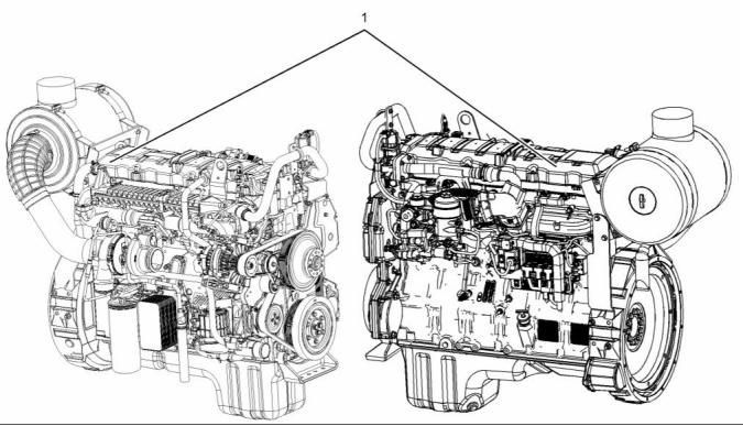
(1) Universal Warning
Do not operate or work on this equipment unless
you have read and understand the instructions
and warnings in the Operation and Maintenance
Manuals. Failure to follow the instructions or
heed the warnings could result in serious injury
or death.
g01154807
Illustration 1
Typical example
This document is printed from SPI². Not for RESALE
![]()
![]()
![]()
![]()
![]()
6
SEBU8455
Safety Section
Safety Messages
g02428016
Illustration 2
(1) Universal warning
The universal warning labels (1) are located on the
rear left side of the valve mechanism cover and the
rear right side of the valve mechanism cover.
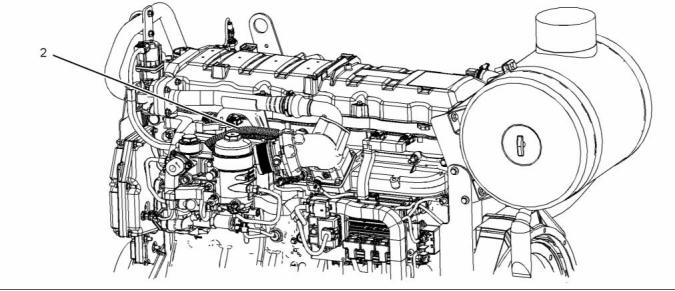
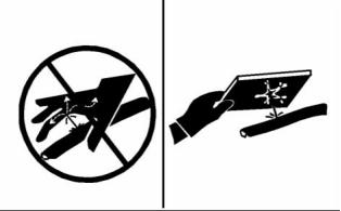
(2) Hand (High Pressure)
Contact with high pressure fuel may cause fluid
penetration and burn hazards. High pressure fu-
el spray may cause a fire hazard. Failure to fol-
low these inspection, maintenance and service in-
structions may cause personal injury or death.
This document is printed from SPI². Not for RESALE
![]()
![]()
![]()
![]()
SEBU8455
7
Safety Section
General Hazard Information
g02835016
Illustration 3
(2) Hand (High Pressure)
The warning label for the Hand (High Pressure)
(2) is a wrap around label that is installed on the
high-pressure oil line.
• Tampering with the engine installation or tampering
with the OEM supplied wiring can be dangerous.
Personal injury, death and/or engine damage could
result.
i04257489
• Vent the engine exhaust to the outside when the
engine is operated in an enclosed area.
General Hazard Information
• Wear a hard hat, protective glasses, and other
protective equipment, as required.
• When work is performed around an engine that is
operating, wear protective devices for ears in order
to help prevent damage to hearing.
• Do not wear loose clothing or jewelry that can snag
on controls or on other parts of the engine.
• Ensure that all protective guards and all covers are
secured in place on the engine.
• Never put maintenance fluids into glass containers.
Glass containers can break.
• Use all cleaning solutions with care.
• Report all necessary repairs.
g00104545
Illustration 4
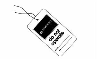
Attach a “Do Not Operate” warning tag or a similar
warning tag to the start switch or to the controls
before the engine is serviced or before the engine is
repaired. Attach the warning tags to the engine and
to each operator control station. When appropriate,
disconnect the starting controls.
Unless other instructions are provided, perform the
maintenance under the following conditions:
• The engine is stopped. Ensure that the engine
cannot be started.
Do not allow unauthorized personnel on the engine,
or around the engine when the engine is being
serviced.
• The protective locks or the controls are in the
applied position.
This document is printed from SPI². Not for RESALE
![]()
![]()
![]()
8
SEBU8455
Safety Section
General Hazard Information
• Disconnect the batteries when maintenance
is performed or when the electrical system is
serviced. Disconnect the battery ground leads.
Tape the leads in order to help prevent sparks.
• Disconnect the connector for the unit injector that
is located on the valve cover base. This will help
prevent personal injury from the high voltage to the
unit injectors. Do not come in contact with the unit
injector terminals while the engine is operating.
• Do not attempt any repairs or any adjustments to
the engine while the engine is operating.
• Do not attempt any repairs that are not understood.
Use the proper tools. Replace any equipment that
is damaged or repair the equipment.
g00702020
Illustration 5
• Wear a hard hat, protective glasses, and other
protective equipment, as required.
• For initial start-up of a new engine or for starting an
engine that has been serviced, make provisions to
stop the engine if an overspeed occurs. This may
be accomplished by shutting off the fuel supply
and/or the air supply to the engine.
• When work is performed around an engine that is
operating, wear protective devices for ears in order
to help prevent damage to hearing.
• Do not wear loose clothing or jewelry that can snag
on controls or on other parts of the engine.
• Start the engine from the operators station (cab).
Never short across the starting motor terminals or
the batteries. This could bypass the engine neutral
start system and/or the electrical system could be
damaged.
• Ensure that all protective guards and all covers are
secured in place on the engine.
• Never put maintenance fluids into glass containers.
Engine exhaust contains products of combustion
which may be harmful to your health. Always start the
engine and operate the engine in a well ventilated
area. If the engine is in an enclosed area, vent the
engine exhaust to the outside.
Glass containers can break.
• Use all cleaning solutions with care.
• Report all necessary repairs.
Cautiously remove the following parts. To help
prevent spraying or splashing of pressurized fluids,
hold a rag over the part that is being removed.
Unless other instructions are provided, perform
the maintenance under the following conditions:
• The engine is stopped. Ensure that the engine
cannot be started.
• Filler caps
• Grease fittings
• Pressure taps
• Breathers
• Disconnect the batteries when maintenance
is performed or when the electrical system is
serviced. Disconnect the battery ground leads.
Tape the leads in order to help prevent sparks.
• Do not attempt any repairs that are not understood.
Use the proper tools. Replace any equipment that
is damaged or repair the equipment.
• Drain plugs
Use caution when cover plates are removed.
Gradually loosen, but do not remove the last two
bolts or nuts that are located at opposite ends of
the cover plate or the device. Before removing the
last two bolts or nuts, pry the cover loose in order to
relieve any spring pressure or other pressure.
Pressurized Air and Water
Pressurized air and/or water can cause debris
and/or hot water to be blown out. This could result in
personal injury.
This document is printed from SPI². Not for RESALE
![]()
![]()
SEBU8455
9
Safety Section
General Hazard Information
Containing Fluid Spillage
When pressurized air and/or pressurized water is
used for cleaning, wear protective clothing, protective
shoes, and eye protection. Eye protection includes
goggles or a protective face shield.
NOTICE
Care must be taken to ensure that fluids are contained
during performance of inspection, maintenance, test-
ing, adjusting and repair of the product. Be prepared to
collect the fluid with suitable containers before open-
ing any compartment or disassembling any compo-
nent containing fluids.
The maximum air pressure for cleaning purposes
must be below 205 kPa (30 psi). The maximum
water pressure for cleaning purposes must be below
275 kPa (40 psi).
Fluid Penetration
Dispose of all fluids according to local regulations and
mandates.
Pressure can be trapped in the hydraulic circuit long
after the engine has been stopped. The pressure can
cause hydraulic fluid or items such as pipe plugs to
escape rapidly if the pressure is not relieved correctly.
Asbestos Information
Do not remove any hydraulic components or parts
until pressure has been relieved or personal injury
may occur. Do not disassemble any hydraulic
components or parts until pressure has been relieved
or personal injury may occur. Refer to the OEM
information for any procedures that are required to
relieve the hydraulic pressure.
g00702022
Illustration 7
Perkins replacement parts that are shipped from
Perkins are asbestos free. Perkins recommends
the use of only genuine Perkins replacement parts.
Use the following guidelines when you handle any
replacement parts that contain asbestos or when you
handle asbestos debris.
Use caution. Avoid inhaling dust that might be
generated when you handle components that contain
asbestos fibers. Inhaling this dust can be hazardous
to your health. The components that may contain
asbestos fibers are brake pads, brake bands, lining
material, clutch plates, and some gaskets. The
asbestos that is used in these components is usually
bound in a resin or sealed in some way. Normal
handling is not hazardous unless airborne dust that
contains asbestos is generated.
g00687600
Illustration 6
Always use a board or cardboard when you check
for a leak. Leaking fluid that is under pressure can
penetrate body tissue. Fluid penetration can cause
serious injury and possible death. A pin hole leak can
cause severe injury. If fluid is injected into your skin,
you must get treatment immediately. Seek treatment
from a doctor that is familiar with this type of injury.
If dust that may contain asbestos is present, there
are several guidelines that should be followed:
• Never use compressed air for cleaning.
• Avoid brushing materials that contain asbestos.
• Avoid grinding materials that contain asbestos.
• Use a wet method in order to clean up asbestos
materials.
This document is printed from SPI². Not for RESALE
![]()
![]()
![]()
![]()
![]()
10
SEBU8455
Safety Section
Burn Prevention
• A vacuum cleaner that is equipped with a high
efficiency particulate air filter (HEPA) can also be
used.
Relieve all pressure in the following systems,
hydraulic system, lubrication system, fuel system,
and the coolant system before the related items are
disconnected.
• Use exhaust ventilation on permanent machining
jobs.
After the engine has stopped, you must wait for 10
minutes in order to allow the pressure to be purged
from the high-pressure lines before any service or
repair is performed on the engine lines.
• Wear an approved respirator if there is no other
way to control the dust.
• Comply with applicable rules and regulations
for the work place. In the United States, use
Occupational Safety and Health Administration
(OSHA) requirements. These OSHA requirements
can be found in “29 CFR 1910.1001”.
Allow the pressure to be purged in the air system, in
the hydraulic system, in the lubrication system, or
in the cooling system before any lines, fittings, or
related items are disconnected.
Induction System
• Obey environmental regulations for the disposal
of asbestos.
• Stay away from areas that might have asbestos
particles in the air.
Sulfuric Acid Burn Hazard may cause serious per-
sonal injury or death.
Dispose of Waste Properly
The exhaust gas cooler may contain a small
amount of sulfuric acid. The use of fuel with sul-
fur levels greater than 15 ppm may increase the
amount of sulfuric acid formed. The sulfuric acid
may spill from the cooler during service of the
engine. The sulfuric acid will burn the eyes, skin
and clothing on contact. Always wear the appro-
priate personal protective equipment (PPE) that
is noted on a material safety data sheet (MSDS)
for sulfuric acid. Always follow the directions for
first aid that are noted on a material safety data
sheet (MSDS) for sulfuric acid.
Coolant
g00706404
Illustration 8
When the engine is at operating temperature, the
engine coolant is hot. The coolant is also under
pressure. The radiator and all lines to the heaters or
to the engine contain hot coolant.
Improperly disposing of waste can threaten the
environment. Potentially harmful fluids should be
disposed of according to local regulations.
Any contact with hot coolant or with steam can cause
severe burns. Allow cooling system components to
cool before the cooling system is drained.
Always use leakproof containers when you drain
fluids. Do not pour waste onto the ground, down a
drain, or into any source of water.
Check that the coolant level after the engine has
stopped and the engine has been allowed to cool.
i04259330
Burn Prevention
Ensure that the filler cap is cool before removing the
filler cap. The filler cap must be cool enough to touch
with a bare hand. Remove the filler cap slowly in
order to relieve pressure.
Do not touch any part of an operating engine
system. Allow the engine system to cool before any
maintenance is performed.
Cooling system conditioner contains alkali. Alkali can
cause personal injury. Do not allow alkali to contact
the skin, the eyes, or the mouth.
This document is printed from SPI². Not for RESALE
![]()
![]()
![]()
![]()
SEBU8455
11
Safety Section
Fire Prevention and Explosion Prevention
Oils
Remove all flammable combustible materials or
conductive materials such as fuel, oil, and debris from
the engine. Do not allow any flammable combustible
materials or conductive materials to accumulate on
the engine.
Hot oil and hot lubricating components can cause
personal injury. Do not allow hot oil to contact the
skin. Also, do not allow hot components to contact
the skin.
Store fuels and lubricants in correctly marked
containers away from unauthorized persons. Store
oily rags and any flammable materials in protective
containers. Do not smoke in areas that are used for
storing flammable materials.
Batteries
Electrolyte is an acid. Electrolyte can cause personal
injury. Do not allow electrolyte to contact the skin or
the eyes. Always wear protective glasses for servicing
batteries. Wash hands after touching the batteries
and connectors. Use of gloves is recommended.
Do not expose the engine to any flame.
Exhaust shields (if equipped) protect hot exhaust
components from oil or fuel spray in case of a line,
a tube, or a seal failure. Exhaust shields must be
installed correctly.
i04259389
Fire Prevention and Explosion
Prevention
Do not weld on lines or tanks that contain flammable
fluids. Do not flame cut lines or tanks that contain
flammable fluid. Clean any such lines or tanks
thoroughly with a nonflammable solvent prior to
welding or flame cutting.
Wiring must be kept in good condition. All electrical
wires must be correctly routed and securely attached.
Check all electrical wires daily. Repair any wires
that are loose or frayed before you operate the
engine. Clean all electrical connections and tighten
all electrical connections.
Eliminate all wiring that is unattached or unnecessary.
Do not use any wires or cables that are smaller than
the recommended gauge. Do not bypass any fuses
and/or circuit breakers.
Arcing or sparking could cause a fire. Secure
connections, recommended wiring, and correctly
maintained battery cables will help to prevent arcing
or sparking.
g00704000
Illustration 9
All fuels, most lubricants, and some coolant mixtures
are flammable.
Inspect all lines and hoses for wear or for
Flammable fluids that are leaking or spilled onto hot
surfaces or onto electrical components can cause
a fire. Fire may cause personal injury and property
damage.
deterioration. The hoses must be correctly routed.
The lines and hoses must have adequate support
and secure clamps. Tighten all connections to the
recommended torque. Leaks can cause fires.
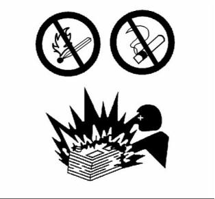
A flash fire may result if the covers for the engine
crankcase are removed within 15 minutes after an
emergency shutdown.
Oil filters and fuel filters must be correctly installed.
The filter housings must be tightened to the correct
torque.
Determine whether the engine will be operated in an
environment that allows combustible gases to be
drawn into the air inlet system. These gases could
cause the engine to overspeed. Personal injury,
property damage, or engine damage could result.
If the application involves the presence of combustible
gases, consult your Perkins dealer and/or your
Perkins distributor for additional information about
suitable protection devices.
This document is printed from SPI². Not for RESALE
![]()
![]()
12
SEBU8455
Safety Section
Fire Prevention and Explosion Prevention
Incorrect jumper cable connections can cause
an explosion that can result in injury. Refer to
the Operation Section of this manual for specific
instructions.
Do not charge a frozen battery. This may cause an
explosion.
The batteries must be kept clean. The covers
(if equipped) must be kept on the cells. Use the
recommended cables, connections, and battery box
covers when the engine is operated.
Fire Extinguisher
Make sure that a fire extinguisher is available. Be
familiar with the operation of the fire extinguisher.
Inspect the fire extinguisher and service the fire
extinguisher regularly. Obey the recommendations
on the instruction plate.
g00704059
Illustration 10
Lines, Tubes, and Hoses
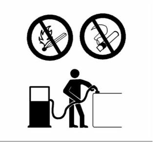
Use caution when you are refueling an engine. Do
not smoke while you are refueling an engine. Do not
refuel an engine near open flames or sparks. Always
stop the engine before refueling.
Do not bend high-pressure lines. Do not strike
high-pressure lines. Do not install any lines that are
bent or damaged. Do not clip any other items to the
high-pressure lines.
Repair any lines that are loose or damaged. Leaks
can cause fires. Consult your Perkins dealer or your
Perkins distributor for repair or for replacement parts.
Check lines, tubes, and hoses carefully. Do not use
your bare hand to check for leaks. Use a board or
cardboard to check for leaks. Tighten all connections
to the recommended torque.
Replace the parts if any of the following conditions
are present:
• End fittings are damaged or leaking.
• Outer coverings are chafed or cut.
• Wires are exposed.
• Outer coverings are ballooning.
• Flexible parts of the hoses are kinked.
• Outer covers have embedded armoring.
• End fittings are displaced.
g00704135
Illustration 11
Gases from a battery can explode. Keep any open
flames or sparks away from the top of a battery. Do
not smoke in battery charging areas.
Never check the battery charge by placing a metal
object across the terminal posts. Use a voltmeter or
a hydrometer.
Make sure that all clamps, guards, and heat shields
are installed correctly. During engine operation, this
will help to prevent vibration, rubbing against other
parts, and excessive heat.
This document is printed from SPI². Not for RESALE
![]()
![]()
![]()
SEBU8455
13
Safety Section
Crushing Prevention and Cutting Prevention
i02143194
High-pressure oil within the high-pressure oil line is
used in order to create high-pressure fuel in the unit
injectors.
Crushing Prevention and
Cutting Prevention
Support the component correctly when work beneath
the component is performed.
Unless other maintenance instructions are provided,
never attempt adjustments while the engine is
running.
Stay clear of all rotating parts and of all moving
parts. Leave the guards in place until maintenance
is performed. After the maintenance is performed,
reinstall the guards.
Keep objects away from moving fan blades. The fan
blades will throw objects or cut objects.
When objects are struck, wear protective glasses in
order to avoid injury to the eyes.
Chips or other debris may fly off objects when objects
are struck. Before objects are struck, ensure that no
one will be injured by flying debris.
i04016709
Mounting and Dismounting
Do not climb on the engine or the engine
aftertreatment. The engine and aftertreatment have
not been designed with mounting or dismounting
locations.
Refer to the OEM for the location of foot and hand
holds for your specific application.
i04553464
High Pressure Oil Lines
Personal injury can result from oil under high
pressure.
DO NOT allow high pressure oil to contact skin.
Wear appropriate protective equipment while
working with high pressure oil systems.
This document is printed from SPI². Not for RESALE
![]()
![]()
![]()
14
SEBU8455
Safety Section
Before Starting Engine
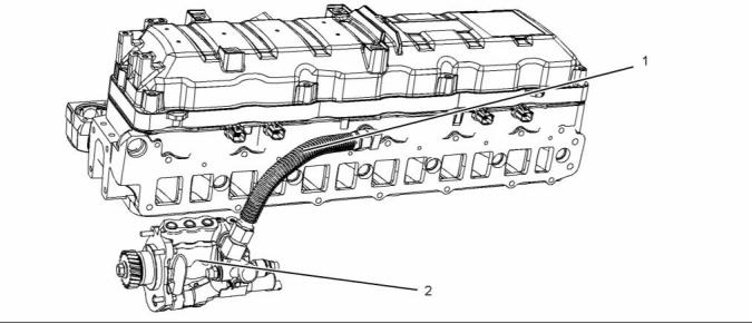
g02722895
Illustration 12
(1) High-pressure oil line
(2) High-pressure oil pump
The high-pressure oil line is the line that is between
the high-pressure oil pump and the high-pressure oil
manifold within the cylinder head. This high-pressure
line is different from fuel lines on other fuel systems.
• Do not operate the engine with a leak. Refer to
Disassembly and Assembly, “High-Pressure Oil
Line- Remove and Install”.
• If the high-pressure oil line is torqued correctly,
and the high-pressure oil line is leaking the
high-pressure oil line must be replaced.
These differences are because of the following items:
• The high-pressure oil line is constantly charged
with high pressure.
• Do not attach any other item to the high-pressure
oil line.
• The internal pressure of the high-pressure oil line
is higher than other types of fuel systems.
i02813489
Do not step on the high-pressure oil line. Do not
deflect the high-pressure oil line. Do not bend or
strike the high-pressure oil line. Deformation or
damage of the high-pressure oil line may cause a
point of weakness and potential failure.
Before Starting Engine
Before the initial start-up of an engine that is new,
serviced or repaired, make provision to shut the
engine off, in order to stop an overspeed. This may
be accomplished by shutting off the air and/or fuel
supply to the engine.
Do not check the high-pressure oil line with the
engine or the starting motor in operation. After the
engine has stopped, wait 10 minutes in order to allow
the pressure to be purged from the high-pressure oil
line, before any service or repair is performed.
Overspeed shutdown should occur automatically for
engines that are controlled electronically. If automatic
shutdown does not occur, press the emergency stop
button in order to cut the fuel and/or air to the engine.
Visually inspect the high-pressure oil line before the
engine is started. This inspection should be each day.
If you inspect the engine in operation, always use
the proper inspection procedure in order to avoid
a fluid penetration hazard. Refer to Operation and
Maintenance Manual, “General hazard Information”.
Inspect the engine for potential hazards.
Before starting the engine, ensure that no one is on,
underneath, or close to the engine. Ensure that the
area is free of personnel.
• Inspect the high-pressure oil line for damage,
deformation, a nick, a cut, a crease, or a dent.
If equipped, ensure that the lighting system for the
engine is suitable for the conditions. Ensure that all
lights work correctly, if equipped.
This document is printed from SPI². Not for RESALE
![]()
![]()
SEBU8455
15
Safety Section
Engine Starting
All protective guards and all protective covers must
be installed if the engine must be started in order
to perform service procedures. To help prevent an
accident that is caused by parts in rotation, work
around the parts carefully.
To ensure that the jacket water heater (if equipped)
is working correctly, check the water temperature
gauge and/or the oil temperature gauge during the
heater operation.
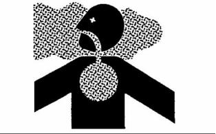
Engine exhaust contains products of combustion
which can be harmful to your health. Always start the
engine and operate the engine in a well ventilated
area. If the engine is started in an enclosed area,
vent the engine exhaust to the outside.
Do not bypass the automatic shutoff circuits. Do not
disable the automatic shutoff circuits. The circuits are
provided in order to help prevent personal injury. The
circuits are also provided in order to help prevent
engine damage.
Note: The engine may be equipped with a device for
cold starting. If the engine will be operated in very
cold conditions, then an extra cold starting aid may
be required. Normally, the engine will be equipped
with the correct type of starting aid for your region
of operation.
See the Service Manual for repairs and for
adjustments.
i02583384
Engine Starting
i02234873
Engine Stopping
Stop the engine according to the procedure in
the Operation and Maintenance Manual, “Engine
Stopping (Operation Section)” in order to avoid
overheating of the engine and accelerated wear of
the engine components.
Use the Emergency Stop Button (if equipped) ONLY
in an emergency situation. Do not use the Emergency
Stop Button for normal engine stopping. After an
emergency stop, DO NOT start the engine until the
problem that caused the emergency stop has been
corrected.
Do not use aerosol types of starting aids such as
ether. Such use could result in an explosion and
personal injury.
If a warning tag is attached to the engine start switch
or to the controls DO NOT start the engine or move
the controls. Consult with the person that attached
the warning tag before the engine is started.
Stop the engine if an overspeed condition occurs
during the initial start-up of a new engine or an engine
that has been overhauled.
To stop an electronically controlled engine, cut the
power to the engine and/or shutting off the air supply
to the engine.
All protective guards and all protective covers must
be installed if the engine must be started in order
to perform service procedures. To help prevent an
accident that is caused by parts in rotation, work
around the parts carefully.
i04259711
Electrical System
Start the engine from the operator's compartment or
from the engine start switch.
Always start the engine according to the procedure
that is described in the Operation and Maintenance
Manual, “Engine Starting” topic in the Operation
Section. Knowing the correct procedure will help to
prevent major damage to the engine components.
Knowing the procedure will also help to prevent
personal injury.
Never disconnect any charging unit circuit or battery
circuit cable from the battery when the charging unit
is operating. A spark can cause the combustible
gases that are produced by some batteries to ignite.
To help prevent sparks from igniting combustible
gases that are produced by some batteries, the
negative “−” cable should be connected last from
the external power source to the primary position for
grounding.
This document is printed from SPI². Not for RESALE
![]()
![]()
![]()
16
SEBU8455
Safety Section
Engine Electronics
,Check the electrical wires daily for wires that
are loose or frayed. Tighten all loose electrical
connections before the engine is started. Repair all
frayed electrical wires before the engine is started.
See the Operation and Maintenance Manual for
specific starting instructions.
The power supply connections and the ground
connections for the engine electronics should always
be from the isolator to the battery.
i04259752
Engine Electronics
Grounding Practices
Tampering with the electronic system installation
or the OEM wiring installation can be dangerous
and could result in personal injury or death and/or
engine damage.
This engine has a comprehensive, programmable
Engine Monitoring System. The Engine Control
Module (ECM) has the ability to monitor the engine
operating conditions. If any of the engine parameters
extend outside an allowable range, the ECM will
initiate an immediate action.
The following actions are available for engine
monitoring control: WARNING, ACTION ALERT, and
SHUTDOWN.
Many of the parameters that are monitored by the
ECM can be programmed for the engine monitoring
functions. The following parameters can be monitored
as a part of the Engine Monitoring System:
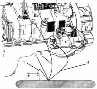
g02430157
Illustration 13
Typical example
(1) Ground to battery
(2) Primary position for grounding
(3) Ground to engine block
(4) Ground to stating motor
• Intake Manifold Air Pressure
• Intake Manifold Temperature
• Coolant Temperature
• Engine Oil Pressure
• Engine Oil Temperature
• Crankshaft Position
• Camshaft Position
Correct grounding for the engine electrical system
is necessary for optimum engine performance
and reliability. Incorrect grounding will result in
uncontrolled electrical circuit paths and in unreliable
electrical circuit paths.
Uncontrolled electrical circuit paths can result in
damage to the crankshaft bearing journal surfaces
and to aluminum components.
Engines that are installed without engine-to-frame
ground straps can be damaged by electrical
discharge.
• Fuel Pressure
• System Voltage
To ensure that the engine and the engine electrical
systems function correctly, an engine-to-frame
ground strap with a direct path to the battery must be
used. This path may be provided by way of a direct
engine ground to the frame.
The Engine Monitoring package can vary for different
engine models and different engine applications.
However, the monitoring system and the engine
monitoring control will be similar for all engines.
The connections for the grounds should be tight and
free of corrosion. The engine alternator must be
grounded to the negative “-” battery terminal with
a wire that is adequate to handle the full charging
current of the alternator.
This document is printed from SPI². Not for RESALE
![]()
![]()
![]()
![]()
SEBU8455
17
Product Information Section
General Information
Product Information
Section
General Information
Model View Illustrations
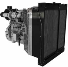
1600D Engine
i04260031
g02757356
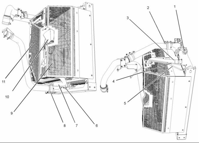
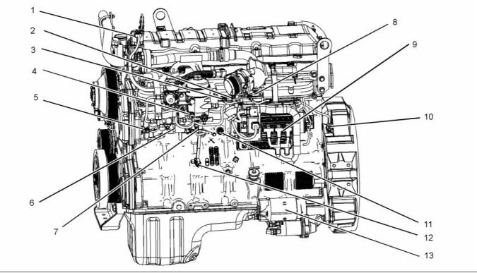
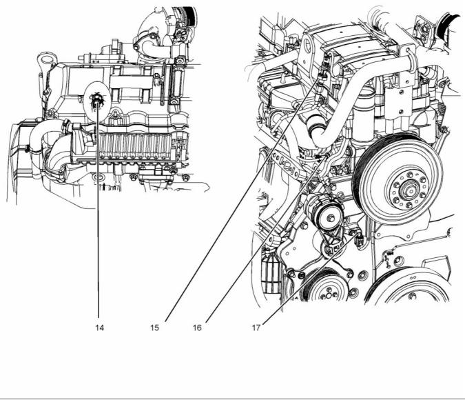
Illustration 14
(1) Rear lifting eye
(2) Front lifting eye
(3) Alternator
(5) Belt tensioner
(6) Coolant pump
(7) Coolant intake connection
(8) Crankcase breather
(9) Oil cooler
(10) Oil filter
(11) Turbocharger
(12) NOx Reduction cooler
(4) Drive belt
This document is printed from SPI². Not for RESALE
![]()
![]()
![]()
18
SEBU8455
Product Information Section
General Information
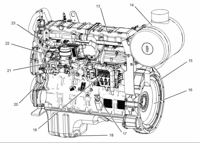
g02430477
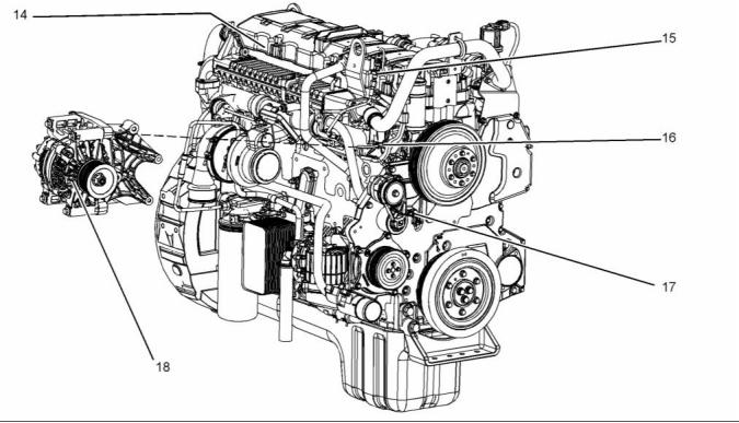
Illustration 15
(13) Valve mechanism cover
(14) Air cleaner
(15) Flywheel housing
(16) Flywheel
(17) Oil filler
(21) Secondary fuel filter
(22) Hand prime pump
(23) Primary fuel filter
(18) Oil drain plug
(19) Control module
(20) High-pressure oil pump
This document is printed from SPI². Not for RESALE
![]()
![]()
SEBU8455
19
Product Information Section
General Information
Coolant System for 1600D Engine
g02430617
Illustration 16
(1) Radiator filler cap
(5) Rear vent liner
(9) Fan guard
(2) Air to air charge cooler connection
(3) Coolant inlet connection
(4) Front vent line
(6) Coolant drain plug
(7) Coolant outlet connection
(8) Air to air charge cooler connection
(10) Fan
(11) Fan guard
This document is printed from SPI². Not for RESALE
![]()
![]()
20
SEBU8455
Product Information Section
General Information
1600A Engine
g02794993
Illustration 17
Typical example
Engine Specifications
i04261592
Product Description
Note: The front end of the engine is opposite the
flywheel end of the engine. The left and the right
sides of the engine are determined from the flywheel
end. The number 1 cylinder is the front cylinder.
The Perkins 1600 Series Industrial Engines has the
following characteristics.
• In-line Six cylinder
• Four stroke cycle
• Turbocharged charge cooled
The 1600 series engines can be divided into
two different engine groups. The 1606A LBSFC
unregulated engine and the 1606D EU stage 3A
compliant engine.
The 1606D engines will have NOx Reduction System
(NRS) installed.
This document is printed from SPI². Not for RESALE
![]()
![]()

SEBU8455
21
Product Information Section
General Information
The diesel fuel is drawn from the fuel tank into a
strainer and into a fuel pump. The fuel pump sends
the fuel into the main fuel filter. From the main fuel
filter the fuel is sent internally to the fuel injectors by
means of an internal fuel manifold. The fuel injectors
use engine lubricating oil from a high-pressure
pump in order to increase the injection pressure.
The injectors are controlled by the engine electronic
control module (ECM).
Aftermarket Products and Perkins
Engines
Perkins does not warrant the quality or performance
of non-Perkins fluids and filters.
g02433836
Illustration 18
Cylinder and valve location
When auxiliary devices, accessories, or consumables
(filters, additives, catalysts,) which are made by other
manufacturers are used on Perkins products, the
Perkins warranty is not affected simply because of
such use.
(A) Inlet valves
(B) Exhaust valves
Table 1
1600 Series Engine Specifications
Operating Range (rpm)
Number of Cylinders
Bore
1500 to 1800
(1)
6 In-Line
However, failures that result from the installation
or use of other manufacturers devices,
accessories, or consumables are NOT Perkins
defects. Therefore, the defects are NOT covered
under the Perkins warranty.
116.6 mm sleeve diameter
146
Stroke
Power
298 to 315 kW
(400 to 422 hp )
(2)
Aspiration
Turbocharged charge
cooled
Compression Ratio
Displacement
17.2 to 1
9.3 L
Firing Order
1-5-3-6-2-4
Counterclockwise
Rotation (flywheel end)
(1) Depending upon application.
(2) Gross power
The crankshaft has a seven main bearing journals, a
fractured split connecting rods is connected to each
crankshaft journal. The pistons have an off set axis
and made from a one piece steel construction. The
cylinder block has wet liners with a single seal. Four
bushing support the camshaft, and the camshaft is
driven by a drive gear. The camshaft operates the
over head valves. Each cylinder has two inlet valves
and, two exhaust valves.
The engine lubricating oil is supplied by a gerotor oil
pump. The engine has an oil cooler and a spin on
oil filter.
This document is printed from SPI². Not for RESALE
![]()
![]()

22
SEBU8455
Product Information Section
Product Identification Information
Product Identification
Table 4
Information
Number of Cylinders
F
6
H
M
R
8
i04266129
Plate Locations and Film
Locations
12
16
Perkins dealers and Perkins distributors require all of
these numbers in order to determine the components
that were included in the engine. This information
permits accurate identification of replacement part
numbers.
Perkins engines are identified by serial numbers.
These numbers are shown on the engine serial
number plate. Perkins distributors need these
numbers in order to determine the components that
were included with the engine. This information
permits accurate identification of replacement part
numbers.
Engine Identification
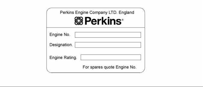
Perkins engines are identified by an engine serial
number.
A typical example of an engine serial number is
XGE F**** U00001W.
X _________________________________________Made in Stafford
G ____________________________________Application (Table 2)
E ________________________________Type of engine (Table 3)
F _________________________Number of cylinders (Table 4)
***** __________________________________Fixed build number
N __________________________________________Built in the USA
00001 ____________________________________Engine Number
W ____________________________________Year of Manufacture
Table 2
Application
G
Genset
Table 3
Type of engine (Diesel)
A
B
D
E
F
TAG1
TAG2
TAG3
TAG4
TAG5
TAG6
H
This document is printed from SPI². Not for RESALE
![]()
![]()

SEBU8455
23
Product Information Section
Product Identification Information
Serial Number Plate (1)
g02435523
Illustration 19
Typical example
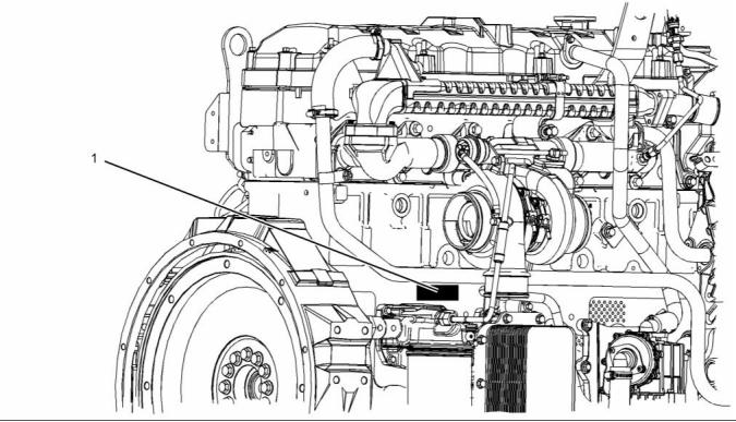
The engine serial number plate is located on right
side of the cylinder block above the engine oil filter.
g02435519
Illustration 20
Typical example
This document is printed from SPI². Not for RESALE
![]()
![]()
![]()
24
SEBU8455
Product Information Section
Product Identification Information
i04266330
Emissions Certification Film
The emission label for the 1600D engine is installed
on rear of the valve mechanism cover.
g02435679
Illustration 21
Typical example
The emission label for the 1600A engine is installed
on rear of the valve mechanism cover.
This document is printed from SPI². Not for RESALE
![]()
![]()
SEBU8455
25
Product Information Section
Product Identification Information
g02834955
Illustration 22
i04266250
Reference Information
Information for the following items may be needed to
order parts. Locate the information for your engine.
Record the information in the appropriate space.
Make a copy of this list for a record. Keep the
information for future reference.
Record for Reference
Engine Model _______________________________________________
Engine Serial number _____________________________________
Engine rpm __________________________________________________
Fuel Strainer ________________________________________________
Fuel Filter Element ________________________________________
Lubrication Oil Filter _______________________________________
Total Lubrication System Capacity _____________________
Total Cooling System Capacity _________________________
Air Cleaner Element _______________________________________
Drive Belt ____________________________________________________
_________________________________________________________________
This document is printed from SPI². Not for RESALE
![]()
![]()
26
SEBU8455
Operation Section
Lifting and Storage
Operation Section
Lifting and Storage
i04823376
Product Storage
Refer to Perkins Engine Company limited, Stafford
for information on engine storage.
i04655490
Product Lifting
There are three different levels of engine storage.
Level “A, B and C”.
Level “A ”
Level “A” will give protection for 12 month for diesel
engines and 12 month protection for gas engines.
This level is for engines that are transported by a
container or a truck. Level “A” is for the transportation
of items that are within the United kingdom and within
Europe.
Level “B ”
This level is additional to level “A”. Level “B ” will
give protection under normal storage condition
from −15° to +55°C (5° to 99°F) and “90%” relative
humidity for 2 year. Level “B” is for the transportation
of items overseas.
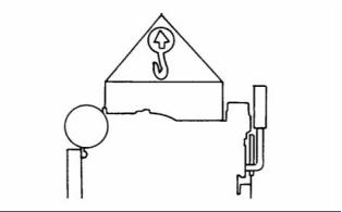
g00103219
Illustration 23
NOTICE
Never bend the eyebolts and the brackets. Only load
the eyebolts and the brackets under tension. Remem-
ber that the capacity of an eyebolt is less as the angle
between the supporting members and the object be-
comes less than 90 degrees.
Level “C ”
In order to protect the product to Level “C”, contact
Perkins Engines Company Limited Stafford.
When it is necessary to remove a component at an
angle, only use a link bracket that is properly rated for
the weight.
Use a hoist to remove heavy components. Use
an adjustable lifting beam to lift the engine. All
supporting members (chains and cables) should be
parallel to each other. The chains and cables should
be perpendicular to the top of the object that is being
lifted.
Some removals require lifting the fixtures in order to
obtain proper balance and safety.
To remove the engine ONLY, use the lifting eyes that
are on the engine.
Lifting eyes are designed and installed for specific
engine arrangements. Alterations to the lifting eyes
and/or the engine make the lifting eyes and the lifting
fixtures obsolete. If alterations are made, ensure
that proper lifting devices are provided. Consult your
Perkins dealer for information regarding fixtures for
proper engine lifting.
This document is printed from SPI². Not for RESALE
![]()
![]()
![]()
![]()
![]()
SEBU8455
27
Operation Section
Features and Controls
Features and Controls
Alarms and Shutoffs
Engine Shutoffs
i04266369
Gauges and Indicators
i04266770
Your engine may not have the same gauges or all of
the gauges that are described. For more information
about the gauge package, see the OEM information.
Gauges provide indications of engine performance.
Ensure that the gauges are in good working order.
Determine the normal operating range by observing
the gauges over a period of time.
The shutoffs are electrically operated or mechanically
operated. The electrically operated shutoffs are
controlled by the ECM.
Noticeable changes in gauge readings indicate
potential gauge or engine problems. Problems may
also be indicated by gauge readings that change
even if the readings are within specifications.
Determine and correct the cause of any significant
change in the readings. Consult your Perkins
distributor for assistance.
Shutoffs are set at critical levels for the following
items:
• Operating temperature
• Operating pressure
• Operating level
NOTICE
If no oil pressure is indicated, STOP the engine. If
maximum coolant temperature is exceeded, STOP
the engine. Engine damage can result.
The particular shutoff may need to be reset before
the engine will start.
NOTICE
Always determine the cause of the engine shutdown.
Make necessary repairs before attempting to restart
the engine.
Engine Oil Pressure – The engine oil
pressure at idle is 103 kPa (15 psi).
• The 1600A oil pressure at full load can range
between 340 to 360 kPa (49 to 52 psi)
Be familiar with the following items:
• Types and locations of the shutoff
• The 1600D oil pressure at full load operates at
370 kPa (53 psi)
• Conditions which cause each shutoff to function
Jacket Water Coolant Temperature –
Typical water temperature into the engine
is 88° to 109°C (190° to 228°F). Higher
temperatures may occur under certain conditions.
The water temperature reading may vary according
to load. The reading should never exceed 109° C
(228° F).
• The resetting procedure that is required to restart
the engine
Engine Alarms
The alarms are electrically operated. The operation
of the alarms is controlled by the ECM.
1. A high water temperature switch is installed in the
cooling system.
The alarm is operated by a sensor or by a switch.
When the sensor or the switch is activated, a signal
is sent to the ECM. An event code is created by
the ECM. The ECM will send a signal in order to
illuminate the lamp.
Tachometer – This gauge indicates engine
speed (rpm).
Your engine may be equipped with the following
sensors or switches:
Ammeter – This gauge indicates the
amount of charge or discharge in the
battery charging circuit. Operation of the
indicator should be to the right side of “0” (zero).
• Engine oil temperature sensor
• Engine oil pressure sensor
• Engine coolant temperature sensor
This document is printed from SPI². Not for RESALE
![]()
![]()
![]()
![]()
![]()
![]()
![]()
![]()
![]()
28
SEBU8455
Operation Section
Features and Controls
Programmable Options and
Systems Operation
Service Hour Meter – The gauge indicates
operating hours of the engine.
i04266490
If the Warning/Derate/Shutdown mode has been
selected and the warning indicator activates,
bring the engine to a stop whenever possible. De-
pending on the application, special precautions
should be taken to avoid personal injury.
Monitoring System
The engine can be programmed to the following
modes:
If the Shutdown mode has been selected and the
warning indicator activates, engine shutdown may
take as little as 20 seconds from the time the warn-
ing indicator is activated. Depending on the ap-
plication, special precautions should be taken to
avoid personal injury. The engine can be restarted
following shutdown for emergency maneuvers, if
necessary.
“Warning”
The orange “Warning” lamp will turn “ON” and the
warning signal is activated continuously in order to
alert the operator that one or more of the engine
parameters is not within normal operating range.
“Derate”
NOTICE
The Engine Monitoring System is not a guarantee
against catastrophic failures. Programmed delays
and derate schedules are designed to minimize false
alarms and provide time for the operator to stop the
engine.
The engine will be derated if the engine exceeds
preset operational limits. The engine derate is
achieved by restricting the amount of fuel that is
available for each injection. The amount of this
reduction of fuel is dependent on the severity of the
fault that has caused the engine derate, typically up
to a limit of 50%. This reduction in fuel results in a
predetermined reduction in engine power.
The following parameters are monitored:
• Coolant temperature
“Shutdown”
• Intake manifold air temperature
• Intake manifold air pressure
• Oil pressure
The orange warning will turn “ON” and the red
shutdown lamp will also turn “ON”.
A shutdown of the engine may occur in as little as
3 seconds. The engine can be restarted after a
shutdown for use in an emergency. However, the
cause of the initial shutdown may still exist. The
engine may shut down again in as little as 3 seconds.
• Oil temperature
• Fuel pressure
• Engine speed/timing
For more information or assistance for repairs,
consult your Perkins distributor or your Perkins
dealer.
• Fuel temperature
• Atmospheric pressure (Barometric pressure)
• Injection control pressure
• Water in fuel switch
i04266532
Sensors and Electrical
Components
The illustrations within the section show the typical
location of the sensors. Specific engines may appear
different from the illustration due to differences in
applications.
This document is printed from SPI². Not for RESALE
![]()
![]()
![]()
![]()
![]()
![]()
![]()
![]()
SEBU8455
29
Operation Section
Features and Controls
g02435937
Illustration 24
(1) Valve for the NOx Reduction System
(NRS)
(2) Manifold absolute pressure sensor
(3) Manifold air temperature sensor
(4) Water in fuel sensor
(5) Engine oil temperature sensor
(6) Injection pressure regulator
(7) Engine fuel pressure sensor
(8) Air inlet heater
(10) Crankshaft position sensor
(11) Coolant jacket heater
(12) Engine oil pressure sensor
(13) Starting motor
(9) Control Module
This document is printed from SPI². Not for RESALE
![]()
![]()
30
SEBU8455
Operation Section
Features and Controls
g02731387
Illustration 25
(14) Injection control pressure sensor
(Internal)
(15) Exhaust back pressure sensor
(16) Engine coolant temperature sensor
(17) Camshaft position sensor
(18) Alternator
Alternator has been shown separately for clarity.
This document is printed from SPI². Not for RESALE
![]()
![]()
SEBU8455
31
Operation Section
Features and Controls
g02740697
Illustration 26
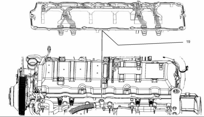
(19) Connector and seal
This document is printed from SPI². Not for RESALE
![]()
![]()
32
SEBU8455
Operation Section
Features and Controls
g02732035
Illustration 27
(1) Valve for the NOx Reduction System
(NRS)
(2) Manifold absolute pressure sensor
(3) Manifold air temperature sensor
(4) Water in fuel sensor
(5) Engine oil temperature sensor
(6) Injection pressure regulator
(7) Engine fuel pressure sensor
(8) Air inlet heater
This document is printed from SPI². Not for RESALE
![]()
![]()
SEBU8455
33
Operation Section
Features and Controls
g02732036
Illustration 28
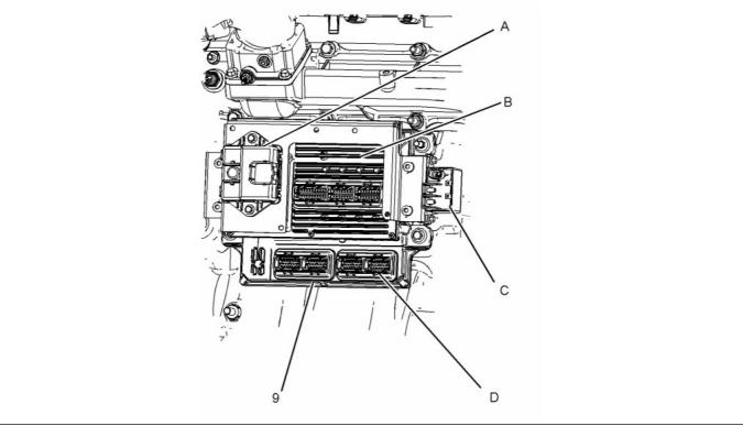
(9) Control module
(A) Driver for the NRS valve
(B) Injection Drive Module (IDM)
(C) High current relay
(D) Electronic Control Module (ECM)
This document is printed from SPI². Not for RESALE
![]()
![]()
34
SEBU8455
Operation Section
Features and Controls
g02732039
Illustration 29
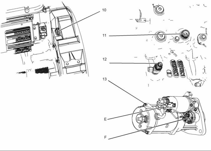
(10) Crankshaft position sensor
(11) Coolant jacket heater
(12) Engine oil pressure sensor
(13) Starting motor
(E) Solenoid
(F) Relay
This document is printed from SPI². Not for RESALE
![]()
![]()
SEBU8455
35
Operation Section
Features and Controls
g02732040
Illustration 30
(14) Injection control pressure sensor
(15) Exhaust back pressure sensor
(16) Coolant temperature sensor
(17) Camshaft position sensor
This document is printed from SPI². Not for RESALE
![]()
![]()
36
SEBU8455
Operation Section
Features and Controls
g02740857
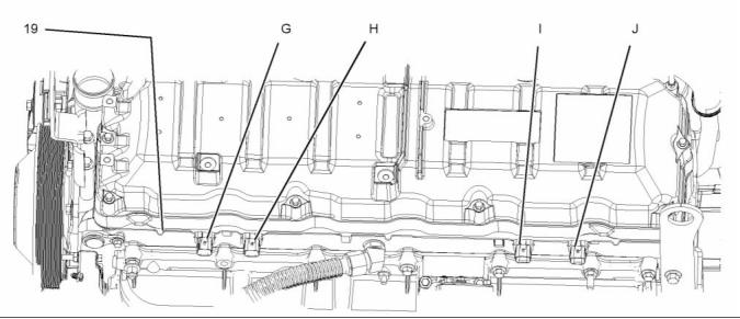
Illustration 31
Item 18 alternator not shown.
(19) Connector and seal
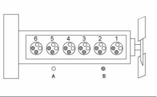
(G) Injection control pressure connection
(H) Connector for injectors 1 and injector 2
(I) Connector for injectors 3 and injector 4
(J) Connector for injectors 5 and injector 6
This document is printed from SPI². Not for RESALE
![]()
![]()
SEBU8455
37
Operation Section
Features and Controls
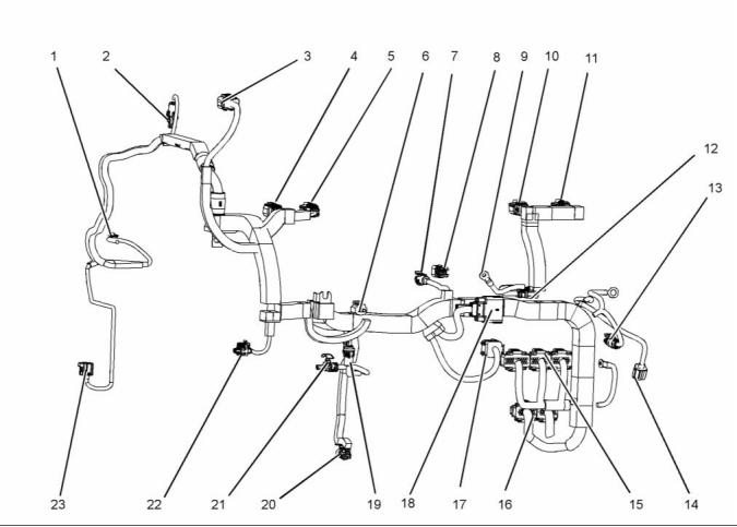
Wiring Harness
g02740876
Illustration 32
(1) Coolant temperature
(2) Exhaust back pressure
(3) NRS
(4) Injection control
(5) Injectors 1 and 2
(6) Water in fuel
(7) Inlet air temperature
(8) Manifold absolute pressure
(9) Inlet heater terminal
(10) Injectors 3 and 4
(11) Injectors 5 and 6
(12) Plug for inlet heater
(13) Relay
(14) Crankshaft position
(15) Injector drive connections
(16) ECM
(17) NRS drive
(18) Customer connection
(19) Low-pressure fuel
(20) Engine oil pressure
(21) Injection pressure regulator
(22) Oil temperature
(23) Camshaft position connection
This document is printed from SPI². Not for RESALE
![]()
![]()
38
SEBU8455
Operation Section
Engine Diagnostics
Engine Diagnostics
i02651197
Engine Operation with Active
Diagnostic Codes
i02784187
Self-Diagnostics
If a diagnostic lamp illuminates during normal engine
operation, the system has identified a situation that is
not within the specification. Use the electronic service
tool to check the active diagnostic codes.
The electronic control module has some
self-diagnostic ability. When an electronic problem
with an input or an output is detected, a diagnostic
code is generated. This indicates the specific problem
with the circuitry.
The active diagnostic code should be investigated.
The cause of the problem should be corrected as
soon as possible. If the cause of the active diagnostic
code is repaired and there is only one active
diagnostic code, the diagnostic lamp will turn off.
A diagnostic code which represents a problem that
currently exists is called an active code.
A diagnostic code that is stored in memory is called
a logged code. Always service active codes prior to
servicing logged codes. Logged codes may indicate
intermittent problems.
Operation of the engine and performance of the
engine can be limited as a result of the active
diagnostic code that is generated. Acceleration rates
may be significantly slower and power outputs may
be automatically reduced. Refer to Troubleshooting
, “Troubleshooting with a Diagnostic Code” for more
information on the relationship between each active
diagnostic code and the possible effect on engine
performance.
Logged codes may not indicate that a repair is
needed. The problems may have been repaired since
the logging of the code. Logged codes may be helpful
to troubleshoot intermittent problems.
i04801080
i02784585
Engine Operation with
Fault Logging
Intermittent Diagnostic Codes
The system provides the capability of Fault Logging.
When the Electronic Control Module (ECM)
generates an active diagnostic code, the code will
be logged in the memory of the ECM. The Perkins
electronic service tool can retrieve codes that have
been logged. The codes that have been logged can
be cleared with the Perkins electronic service tool.
If a diagnostic lamp illuminates during normal engine
operation and the diagnostic lamp shuts OFF, an
intermittent fault may have occurred. If a fault has
occurred, the fault will be logged into the memory of
the Electronic Control Module (ECM).
In most cases, it is not necessary to stop the engine
because of an intermittent code. However, the
operator should retrieve the logged fault codes
and the operator should reference the appropriate
information in order to identify the nature of the fault.
The operator should log any observation that could
have caused the lamp to light.
• Low power
• Limits of the engine speed
• Excessive smoke, etc
This information can be useful to help troubleshoot
the situation. The information can also be used for
future reference. For more information on diagnostic
codes, refer to the Troubleshooting guide for this
engine.
This document is printed from SPI². Not for RESALE
![]()
SEBU8455
39
Operation Section
Engine Starting
Engine Starting
i02815193
Cold Weather Starting
i04268175
Before Starting Engine
Do not use aerosol types of starting aids such as
ether. Such use could result in an explosion and
personal injury.
Before the engine is started, perform the required
daily maintenance and any other periodic
maintenance that is due. Refer to the Operation
and Maintenance Manual, “Maintenance Interval
Schedule” for more information.
The engine will start at a temperature of −10 °C
(14 °F). The ability to start at temperatures below
10 °C (50 °F) will improve by the use of a cylinder
block coolant heater or a device which heats the
crankcase oil. This will help to reduce white smoke
and misfires when the engine is started in cold
weather.
• Open the fuel supply valve (if equipped).
NOTICE
All valves in the fuel return line must be open before
and during engine operation to help prevent high fuel
pressure. High fuel pressure may cause filter housing
failure or other damage.
If the engine has not been run for several weeks, fuel
may have drained. Air may have moved into the filter
housing. Also, when fuel filters have been changed,
some air will be left in the filter housing. Refer to
Operation and Maintenance Manual, “Fuel System -
Prime” in order to remove air from the fuel system.
If the engine has not been started for several weeks,
fuel may have drained from the fuel system. Air
may have entered the filter housing. Also, when fuel
filters have been changed, some air pockets will be
trapped in the engine. In these instances, prime the
fuel system. Refer to the Operation and Maintenance
Manual, “Fuel System - Prime” for more information
on priming the fuel system.
Use the procedure that follows for cold weather
starting.
NOTICE
Do not engage the starting motor when flywheel is
turning. Do not start the engine under load.
If the engine fails to start within 30 seconds, release
the starter switch or button and wait thirty seconds to
allow the starting motor to cool before attempting to
start the engine again.
Engine exhaust contains products of combustion
which may be harmful to your health. Always start
and operate the engine in a well ventilated area
and, if in an enclosed area, vent the exhaust to the
outside.
1. If equipped, press the start button. If equipped,
turn the keyswitch to the START position in order
to engage the electric starting motor and crank
the engine.
• Do not start the engine or move any of the controls
if there is a “DO NOT OPERATE” warning tag or
similar warning tag attached to the start switch or
to the controls.
2. Repeat step 1 three times if the engine fails to
• Reset all of the shutoffs or alarm components (if
equipped).
start.
3. If the engine fails to start, investigate the problem.
Use the Perkins electronic service tool. A system
fault may be indicated after the engine is started. If
this occurs the ECM has detected a problem with
the system. Investigate the cause of the problem.
Use the Perkins electronic service tool.
• Ensure that any equipment that is driven by the
engine has been disengaged from the engine.
Minimize electrical loads or remove any electrical
loads.
• Ensure that the coolant level is correct.
• Ensure that the engine oil level is correct.
Note: Oil pressure should rise within 15 seconds
after the engine starts. The electronic engine controls
monitor the oil pressure. The electronic controls will
stop the engine if the oil pressure is below normal.
This document is printed from SPI². Not for RESALE
![]()
![]()
![]()
![]()
![]()
![]()
![]()
![]()
![]()
40
SEBU8455
Operation Section
Engine Starting
4. Operate the engine at no load until all the coolant
temperature starts to rise. Check the gauges
during the warm-up period.
i04268176
Starting the Engine
Note: The oil pressures and fuel pressures should
be in the normal range on the instrument panel. Do
not apply a load to the engine until the oil pressure
gauge indicates at least normal pressure. Inspect the
engine for leaks and/or unusual noises.
Note: Do not adjust the engine speed control during
start-up. The electronic control module (ECM) will
control the engine speed during start-up.
Starting the Engine
Note: After the ECM has completed the cold mode,
cold mode cannot be enabled again until the ECM is
switched OFF.
1. Disengage any equipment that is driven by the
engine.
Note: Do not attempt to restart the engine until the
engine has completely stopped.
2. Turn the keyswitch to the ON position and wait for
the wait to stat lamp to go off.
Note: The air inlet heat will be required in low
ambient temperatures. The ECM will decide if the air
heater element will be required to warn the intake air
in order to start the engine.
3. Turn the keyswitch to the START position.
Release the keyswitch when the engine starts.
The keyswitch will return to the ON position.
NOTICE
Do not engage the starting motor when flywheel is
turning. Do not start the engine under load.
If the engine fails to start within 30 seconds, release
the starter switch or button and wait two minutes to
allow the starting motor to cool before attempting to
start the engine again.
4. With the engine in operation check the oil
pressure. Oil pressure should be 103 kPa (15 psi)
within seconds of engine operation, if oil pressure
is incorrect, stop the engine and investigate
immediately. If the engine cannot reach minimum
oil pressure 276 kPa (40 psi) or other warning
are activated, stop the engine and investigate
immediately.
5. If the engine fails to start, repeat steps 2 to step 3.
6. If the engine fails to start after three attempts,
determine the cause.
This document is printed from SPI². Not for RESALE
![]()
![]()
![]()
SEBU8455
41
Operation Section
Engine Starting
i02428473
Starting with Jump Start
Cables
Do not use jump start cables in order to start the
engine. Charge the batteries or replace the batteries.
Refer to Operation and Maintenance Manual,
“Battery - Replace”.
i01646248
After Starting Engine
Note: In temperatures from 0 to 60°C (32 to 140°F),
the warm-up time is approximately three minutes. In
temperatures below 0°C (32°F), additional warm-up
time may be required.
Note: Ensure that the self test for the monitoring
system (if equipped) is completed before operating
the engine under load.
When the engine idles during warm-up, observe the
following conditions:
• Check for any fluid or for any air leaks at idle rpm
and at one-half full rpm (no load on the engine)
before operating the engine under load. This is not
possible in some applications.
• Operate the engine at low idle until all systems
achieve operating temperatures. Check all gauges
during the warm-up period.
Note: Gauge readings should be observed and
the data should be recorded frequently while the
engine is operating. Comparing the data over time
will help to determine normal readings for each
gauge. Comparing data over time will also help
detect abnormal operating developments. Significant
changes in the readings should be investigated.
This document is printed from SPI². Not for RESALE
![]()
42
SEBU8455
Operation Section
Engine Operation
Engine Operation
i02583385
Fuel Conservation Practices
i02578030
Engine Operation
The efficiency of the engine can affect the fuel
economy. Perkins design and technology in
manufacturing provides maximum fuel efficiency in
all applications. Follow the recommended procedures
in order to attain optimum performance for the life
of the engine.
Correct operation and maintenance are key factors
in obtaining the maximum life and economy of
the engine. If the directions in the Operation and
Maintenance Manual are followed, costs can be
minimized and engine service life can be maximized.
• Avoid spilling fuel.
Gauge readings should be observed and the data
should be recorded frequently while the engine
is operating. Comparing the data over time will
help to determine normal readings for each gauge.
Comparing data over time will also he, lp detect
abnormal operating developments. Significant
changes in the readings should be investigated.
Fuel expands when the fuel is warmed up. The fuel
may overflow from the fuel tank. Inspect fuel lines for
leaks. Repair the fuel lines, as needed.
• Be aware of the properties of the different fuels.
Use only the recommended fuels.
• Avoid unnecessary operation at no load.
Shut off the engine instead of operating the engine
at no load for long periods of time.
• Observe the service indicator for the air cleaner
frequently, if equipped. Keep the air cleaner
elements clean.
• Maintain a good electrical system.
One bad battery cell will overwork the alternator. This
will consume excess power and excess fuel.
• Ensure that the belts are properly adjusted. The
belts should be in good condition.
• Ensure that all of the connections of the hoses are
tight. The connections should not leak.
• Ensure that the driven equipment is in good
working order.
• Cold engines consume excess fuel. Keep cooling
system components clean and keep cooling
system components in good repair. Never operate
the engine without water temperature regulators.
All of these items will help maintain operating
temperatures.
This document is printed from SPI². Not for RESALE
![]()
SEBU8455
43
Operation Section
Cold Weather Operation
Cold Weather Operation
Personal injury or property damage can result
from alcohol or starting fluids.
i04564559
Cold Weather Operation
Alcohol or starting fluids are highly flammable and
toxic and if improperly stored could result in injury
or property damage.
Perkins Diesel Engines can operate effectively in
cold weather. During cold weather, the starting and
the operation of the diesel engine is dependent on
the following items:
Do not use aerosol types of starting aids such as
ether. Such use could result in an explosion and
personal injury.
• The type of fuel that is used
• The viscosity of the engine oil
• Optional Cold starting aid
• Battery condition
Viscosity of the Engine Lubrication
Oil
Correct engine oil viscosity is essential. Oil viscosity
affects the amount of torque that is needed
to crank the engine. Refer to Operation and
Maintenance Manual, “Fluid Recommendations” for
the recommended viscosity of oil.
The operation and maintenance of an engine in
freezing temperatures is complex , because of the
following conditions:
• Weather conditions
• Engine applications
Recommendations for the Coolant
Provide cooling system protection for the lowest
expected outside temperature. Refer to this Operation
and Maintenance Manual, “Fluid Recommendations”
for the recommended coolant mixture.
Recommendations from your Perkins distributor are
based on past proven practices. The information that
is contained in this section provides guidelines for
cold-weather operation.
In cold weather, check the coolant often for the
correct glycol concentration in order to ensure
adequate freeze protection.
Hints for Cold Weather Operation
• If the engine will start, operate the engine until a
minimum operating temperature of 81 °C (177.8 °F)
is achieved. Achieving operating temperature will
help prevent the intake valves and exhaust valves
from sticking.
Coolant Jacket Heaters
If installed, the coolant jacket heater heats the engine
jacket coolant that surrounds the cylinder block. This
added heat provides the following function:
• The cooling system and the lubrication system
for the engine do not lose heat immediately upon
shutdown. This means that an engine can be shut
down for a time and the engine can still have the
ability to start readily.
• Startability is improved.
An electric heater can be activated once the engine
is stopped. An effective heater is typically a 1250
W at 120 V. If your engine is to operate in a cold
environment, consult your Perkins distributor for more
information. An oil pan heater may also be required.
• Install the correct specification of engine lubricant
before the beginning of cold weather.
• Check all rubber parts (hoses, drive belts,) weekly.
• Check all electrical wiring and connections for any
fraying or damaged insulation.
• Keep all batteries fully charged and warm.
• Check the air cleaners and the air intake daily.
This document is printed from SPI². Not for RESALE
![]()
![]()
![]()
![]()
![]()
44
SEBU8455
Operation Section
Cold Weather Operation
i02576035
• A lower energy per unit volume of fuel
Fuel and the Effect from Cold
Weather
Note: Group 3 fuels reduce the life of the engine. The
use of Group 3 fuels is not covered by the Perkins
warranty.
Group 3 fuels include Low Temperature Fuels and
Aviation Kerosene Fuels.
Note: Only use grades of fuel that are recommended
by Perkins. Refer to this Operation and Maintenance
Manual, “Fluid Recommendations”.
Special fuels include Biofuel.
The cloud point is a temperature that allows wax
crystals to form in the fuel. These crystals can cause
the fuel filters to plug.
The following fuels can be used in this series of
engine.
• Group 1
The pour point is the temperature when diesel fuel
will thicken. The diesel fuel becomes more resistant
to flow through fuel lines, fuel filters,and fuel pumps.
• Group 2
• Group 3
Be aware of these facts when diesel fuel is
purchased. Consider the average ambient air
temperature for the engine's application. Engines that
are fueled in one climate may not operate well if the
engines are moved to another climate. Problems can
result due to changes in temperature.
• Special Fuels
Perkins prefer only Group 1 and Group 2 fuels for
use in this series of engines.
Group 1 fuels are the preferred Group of Fuels for
general use by Perkins. Group 1 fuels maximize
engine life and engine performance. Group 1 fuels
are usually less available than Group 2 fuels.
Frequently, Group 1 fuels are not available in colder
climates during the winter.
Before troubleshooting for low power or for poor
performance in the winter, check the fuel for waxing.
Low temperature fuels may be available for engine
operation at temperatures below 0 °C (32 °F). These
fuels limit the formation of wax in the fuel at low
temperatures.
Note: Group 2 fuels must have a maximum wear
scar of 650 micrometers (HFRR to ISO 12156-1).
For more information on cold weather operation, refer
to the Operation and Maintenance Manual, “Cold
Weather Operation and Fuel Related Components in
Cold Weather”.
Group 2 fuels are considered acceptable for issues
of warranty. This group of fuels may reduce the life
of the engine, the engine's maximum power, and the
engine's fuel efficiency.
When Group 2 diesel fuels are used the following
components provide a means of minimizing problems
in cold weather:
• Glow plugs (if equipped)
• Engine coolant heaters, which may be an OEM
option
• Fuel heaters, which may be an OEM option
• Fuel line insulation, which may be an OEM option
There are three major differences between Group
1 fuels and Group 2 fuels. Group 1 fuels have the
following different characteristics to Group 2 fuels.
• A lower cloud point
• A lower pour point
This document is printed from SPI². Not for RESALE
![]()
SEBU8455
45
Operation Section
Cold Weather Operation
i04268370
Fuel Related Components in
Cold Weather
Fuel Tanks
Condensation can form in partially filled fuel tanks.
Top off the fuel tanks after you operate the engine.
Fuel tanks should contain some provision for draining
water and sediment from the bottom of the tanks.
Some fuel tanks use supply pipes that allow water
and sediment to settle below the end of the fuel
supply pipe.
Some fuel tanks use supply lines that take fuel
directly from the bottom of the tank. If the engine is
equipped with this system, regular maintenance of
the fuel system filter is important.
Drain the water and sediment from any fuel storage
tank at the following intervals: weekly, oil changes,
and refueling of the fuel tank. This draining will help
prevent water and/or sediment from being pumped
from the fuel storage tank and into the engine fuel
tank.
Fuel Filter
A strainer and fuel filter is installed between the
fuel tank and the electronic fuel injectors. After you
change the fuel filter, always prime the fuel system
in order to remove air bubbles from the fuel system.
Refer to the Operation and Maintenance Manual in
the Maintenance Section for more information on
priming the fuel system.
This document is printed from SPI². Not for RESALE
![]()
46
SEBU8455
Operation Section
Engine Stopping
Engine Stopping
i02583411
After Stopping Engine
i04268255
Stopping the Engine
Note: Before you check the engine oil, do not operate
the engine for at least 10 minutes in order to allow
the engine oil to return to the oil pan.
NOTICE
• Check the crankcase oil level. Maintain the oil level
between the “LOW” mark and the “HIGH” mark on
the oil level gauge.
Stopping the engine immediately after it has been
working under load, can result in overheating and ac-
celerated wear of the engine components.
Note: Only use oil that is recommended in
this Operation and Maintenance Manual, “Fluid
Recommendations”. Failure to use the recommended
oil may result in engine damage.
Avoid accelerating the engine prior to shutting it down.
Avoiding hot engine shutdowns will maximize tur-
bocharger shaft and bearing life.
• If necessary, perform minor adjustments. Repair
any leaks and tighten any loose bolts.
Note: Individual applications will have different
control systems. Ensure that the shutoff procedures
are understood. Use the following general guidelines
in order to stop the engine.
• Note the service hour meter reading. Perform
the maintenance that is in the Operation and
Maintenance Manual, “Maintenance Interval
Schedule”.
1. Remove the load from the engine. Allow the
engine to run under no load conditions for 5
minutes in order to cool the engine.
• Fill the fuel tank in order to help prevent
accumulation of moisture in the fuel. Do not overfill
the fuel tank.
2. Stop the engine after the cool down period
according to the shutoff system on the engine and
turn the ignition keyswitch to the OFF position.
If necessary, refer to the instructions that are
provided by the OEM.
• Allow the engine to cool. Check the coolant level.
Maintain the cooling system at 13 mm (0.5 inch)
from the bottom of the pipe for filling.
Note: Only use coolant that is recommended in
this Operation and Maintenance Manual, “Fluid
Recommendations”. Failure to use the recommended
oil may result in engine damage.
i01903586
Emergency Stopping
• If freezing temperatures are expected, check
the coolant for proper antifreeze protection. The
cooling system must be protected against freezing
to the lowest expected outside temperature. Add
the proper coolant/water mixture, if necessary.
NOTICE
Emergency shutoff controls are for EMERGENCY use
ONLY. DO NOT use emergency shutoff devices or
controls for normal stopping procedure.
• Perform all required periodic maintenance on all
driven equipment. This maintenance is outlined in
the instructions from the OEM.
The OEM may have equipped the application with
an emergency stop button. For more information
about the emergency stop button, refer to the OEM
information.
Ensure that any components for the external system
that support the engine operation are secured after
the engine is stopped.
This document is printed from SPI². Not for RESALE
![]()
![]()
![]()
![]()
![]()
SEBU8455
47
Maintenance Section
Refill Capacities
Maintenance Section
i04268521
Fluid Recommendations
Refill Capacities
• Glossary
i04268391
• ISO International Standards Organization
• ASTM American Society for Testing and Materials
Refill Capacities
• HFRR High Frequency Reciprocating Rig for
Lubricity testing of diesel fuels
Lubrication System
• FAME Fatty Acid Methyl Esters
• CFR Co-ordinating Fuel Research
• LSD Low Sulfur Diesel
The refill capacities for the engine crankcase
reflect the approximate capacity of the crankcase
or sump plus standard oil filters. Auxiliary oil filter
systems will require additional oil. Refer to the OEM
specifications for the capacity of the auxiliary oil filter.
Refer to the Operation and Maintenance Manual,
“Maintenance Section” for more information on
Lubricant Specifications.
• RME Rape Methyl Ester
• SME Soy Methyl Ester
Table 5
• EPA Environmental Protection Agency of the
United States
Engine
Refill Capacities
Compartment or System
Crankcase Oil Sump
Maximum
General Information
(1)
35.96 L (7.9Imp gal)
NOTICE
(1) These values are the approximate capacities for the crankcase
Every attempt is made to provide accurate, up-to-date
information. By use of this document you agree that
Perkins Engines Company Limited is not responsible
for errors or omissions.
oil sump which includes the standard factory installed oil filters.
Engines with auxiliary oil filters will require additional oil. Refer
to the OEM specifications for the capacity of the auxiliary oil
filter.
Cooling System
NOTICE
These recommendations are subject to change with-
out notice. Contact your local Perkins distributor for
the most up-to-date recommendations.
Refer to the OEM specifications for the External
System capacity. This capacity information will be
needed in order to determine the amount of coolant
that is required for the Total Cooling System.
Table 6
Diesel Fuel Requirements
Engine
Refill Capacities
Perkins is not in a position to continuously evaluate
and monitor all worldwide distillate diesel fuel
specifications that are published by governments and
technological societies.
Compartment or System
11.8 L
1600A Engine Only
(2.6 Imp gal)
Table 7 provides a known reliable baseline in order
to judge the expected performance of distillate diesel
fuels that are derived from conventional sources.
30.9 L
1600A Total System
(6.8 Imp gal)
13.2 L
1600D Engine Only
(2.9 Imp gal)
Satisfactory engine performance is dependent on
the use of a good quality fuel. The use of a good
quality fuel will give the following results: long engine
life and acceptable exhaust emissions levels. The
fuel must meet the minimum requirements that are
stated in table 7.
32.3 L
1600D Total System
(7.1 Imp gal)
This document is printed from SPI². Not for RESALE
免費(fèi)熱線
400-100-8969???15088860848
400-100-8969???15088860848
機(jī)組銷售
0574-26871589? 15267810868
0574-26871589? 15267810868
配件銷售
0574-26886646? 15706865167
0574-26886646? 15706865167
維修熱線
0574-26871569 18658287286
0574-26871569 18658287286
手機(jī)端

微信公眾號
在線客服