 English
 Espaol
 Franais
 阿拉伯
阿拉伯 中文(簡)
中文(簡) Deutsch
 Italiano
 Português
 日本
日本 韓國
韓國 български
 hrvatski
 esky
esky Dansk
Dansk Nederlands
 suomi
suomi Ελληνικ
 印度
印度 norsk
norsk Polski
 Roman
Roman русский
 Svenska
 珀金斯Perkins2206D-E13TA操作保養,珀金斯Perkins2206D-E13TA操作保養技術支持中心,珀金斯Perkins2206D-E13TA操作保養代理商,珀金斯Perkins2206D-E13TA操作保養銷售服務中心,珀金斯Perkins2206D-E13TA操作保養價格規格資料查詢,寧波日昕動力科技有限公司

珀金斯Perkins2206D-E13TA操作保養
詳細描述
Operation and
Maintenance
Manual
2206D-E13TA Industrial Engine
Table of Contents
Refill Capacities....................... ....................... 39
Maintenance Recommendations.......... .......... 54
Maintenance Interval Schedule........... ........... 57
Warranty Section
Foreword.............................. ............................. 4
Safety Section
Safety Messages....................... ....................... 5
General Hazard Information............... .............. 6
Burn Prevention....................... ....................... 10
Fire Prevention and Explosion Prevention ... .. 10
Crushing Prevention and Cutting Prevention . 12
Mounting and Dismounting............... .............. 12
Before Starting Engine ................. .................. 12
Engine Starting........................ ....................... 13
Engine Stopping....................... ...................... 13
Electrical System...................... ...................... 13
Engine Electronics..................... ..................... 14
Product Information Section
Warranty Information................... ................... 82
Reference Information Section
Reference Materials ........................................ 83
Index Section
Index................................ ............................... 86
General Information.................... .................... 15
Product Identification Information.......... ......... 18
Operation Section
Lifting and Storage..................... ..................... 20
Features and Controls.................. .................. 23
Engine Diagnostics..................... .................... 28
Engine Starting........................ ....................... 30
Engine Operation...................... ...................... 34
Cold Weather Operation................. ................ 36
Engine Stopping....................... ...................... 38
Maintenance Section
This document has been printed from SPI2. NOT FOR RESALE
![]()
4
SEBU9072
Foreword
Foreword
Recommended service should be performed at the
appropriate intervals as indicated in the Maintenance
Interval Schedule. The actual operating environment
of the engine also governs the Maintenance Interval
Schedule. Therefore, under extremely severe, dusty,
wet or freezing cold operating conditions, more
frequent lubrication and maintenance than is
specified in the Maintenance Interval Schedule may
be necessary.
Literature Information
This manual contains safety, operation instructions,
lubrication and maintenance information. This manual
should be stored in or near the engine area in a
literature holder or literature storage area. Read,
study and keep it with the literature and engine
information.
The maintenance schedule items are organized for a
preventive maintenance management program. If the
preventive maintenance program is followed, a
periodic tune-up is not required. The implementation
of a preventive maintenance management program
should minimize operating costs through cost
avoidances resulting from reductions in unscheduled
downtime and failures.
English is the primary language for all Perkins
publications. The English used facilitates translation
and consistency.
Some photographs or illustrations in this manual
show details or attachments that may be different
from your engine. Guards and covers may have been
removed for illustrative purposes. Continuing
improvement and advancement of product design
may have caused changes to your engine which are
not included in this manual. Whenever a question
arises regarding your engine, or this manual, please
consult with your Perkins dealer or your Perkins
distributor for the latest available information.
Maintenance Intervals
Perform maintenance on items at multiples of the
original requirement. We recommend that the
maintenance schedules be reproduced and displayed
near the engine as a convenient reminder. We also
recommend that a maintenance record be maintained
as part of the engine's permanent record.
Safety
Your authorized Perkins dealer or your Perkins
distributor can assist you in adjusting your
maintenance schedule to meet the needs of your
operating environment.
This safety section lists basic safety precautions. In
addition, this section identifies hazardous, warning
situations. Read and understand the basic
precautions listed in the safety section before
operating or performing lubrication, maintenance and
repair on this product.
Overhaul
Major engine overhaul details are not covered in the
Operation and Maintenance Manual except for the
interval and the maintenance items in that interval.
Major repairs should only be carried out by Perkins
authorized personnel. Your Perkins dealer or your
Perkins distributor offers a variety of options
regarding overhaul programs. If you experience a
major engine failure, there are also numerous after
failure overhaul options available. Consult with your
Perkins dealer or your Perkins distributor for
information regarding these options.
Operation
Operating techniques outlined in this manual are
basic. They assist with developing the skills and
techniques required to operate the engine more
efficiently and economically. Skill and techniques
develop as the operator gains knowledge of the
engine and its capabilities.
The operation section is a reference for operators.
Photographs and illustrations guide the operator
through procedures of inspecting, starting, operating
and stopping the engine. This section also includes a
discussion of electronic diagnostic information.
California Proposition 65 Warning
Diesel engine exhaust and some of its constituents
are known to the State of California to cause cancer,
birth defects, and other reproductive harm. Battery
posts, terminals and related accessories contain lead
and lead compounds. Wash hands after handling.
Maintenance
The maintenance section is a guide to engine care.
The illustrated, step-by-step instructions are grouped
by service hours and/or calendar time maintenance
intervals. Items in the maintenance schedule are
referenced to detailed instructions that follow.
This document has been printed from SPI2. NOT FOR RESALE
![]()
SEBU9072
5
Safety Section
Safety Messages
Safety Section
i06218430
Safety Messages
There may be several specific safety messages on
your engine. The exact location and a description of
the safety messages are reviewed in this section.
Become familiar with all safety messages.
Ensure that all of the safety messages are legible.
Clean the safety messages or replace the safety
messages if the words cannot be read or if the
illustrations are not visible. Use a cloth, water, and
soap to clean the safety messages. Do not use
solvents, gasoline, or other harsh chemicals.
Solvents, gasoline, or harsh chemicals could loosen
the adhesive that secures the safety messages. The
safety messages that are loosened could drop off the
engine.
Replace any safety message that is damaged or
missing. If a safety message is attached to a part of
the engine that is replaced, install a new safety
message on the replacement part. Your Perkins
distributor can provide new safety messages.
Illustration 1
g03859164
Typical example
This document has been printed from SPI2. NOT FOR RESALE
![]()
![]()
6
SEBU9072
Safety Section
General Hazard Information
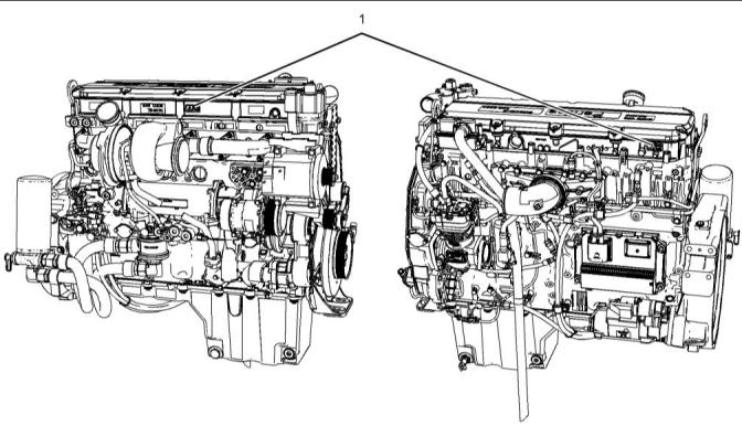
Universal Warning (1)
Do not allow unauthorized personnel on the engine,
or around the engine when the engine is being
serviced.
• Tampering with the engine installation or tampering
with the OEM supplied wiring can be dangerous.
Personal injury, death and/or engine damage
could result.
• Vent the engine exhaust to the outside when the
engine is operated in an enclosed area.
• If the engine is not running, do not release the
secondary brake or the parking brake systems
unless the vehicle is blocked or unless the vehicle
is restrained.
• Wear a hard hat, protective glasses, and other
protective equipment, as required.
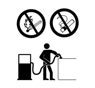
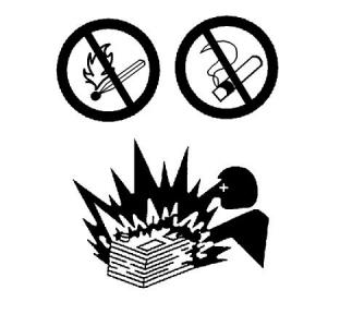
Illustration 2
g01370904
One safety message is located on the left side of the
engine. One safety message is located on the right
side of the engine.
• When work is performed around an engine that is
operating, wear protective devices for ears in order
to help prevent damage to hearing.
• Do not wear loose clothing or jewelry that can snag
on controls or on other parts of the engine.
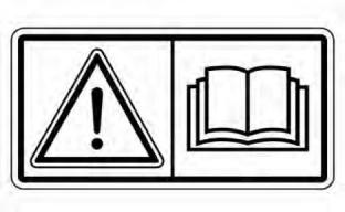
Do not operate or work on this equipment unless
you have read and understand the instructions
and warnings in the Operation and Maintenance
Manuals. Failure to follow the instructions or heed
the warnings could result in serious injury or
death.
• Ensure that all protective guards and all covers are
secured in place on the engine.
• Never put maintenance fluids into glass
containers. Glass containers can break.
• Use all cleaning solutions with care.
• Report all necessary repairs.
i06106934
General Hazard Information
Unless other instructions are provided, perform the
maintenance under the following conditions:
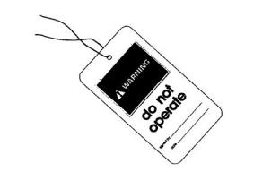
Illustration 3
g00104545
Attach a “Do Not Operate” warning tag or a similar
warning tag to the start switch or to the controls
before the engine is serviced or before the engine is
repaired. Attach the warning tags to the engine and to
each operator control station. When appropriate,
disconnect the starting controls.
This document has been printed from SPI2. NOT FOR RESALE
![]()
![]()
![]()
![]()
![]()
![]()
![]()
SEBU9072
7
Safety Section
General Hazard Information
• The engine is stopped. Ensure that the engine
cannot be started.
• Filler caps
• Grease fittings
• Pressure taps
• Breathers
• The protective locks or the controls are in the
applied position.
• Engage the secondary brakes or parking brakes.
• Drain plugs
• Block the vehicle or restrain the vehicle before
maintenance or repairs are performed.
Use caution when cover plates are removed.
Gradually loosen, but do not remove the last two bolts
or nuts that are located at opposite ends of the cover
plate or the device. Before removing the last two bolts
or nuts, pry the cover loose in order to relieve any
spring pressure or other pressure.
• Disconnect the batteries when maintenance is
performed or when the electrical system is
serviced. Disconnect the battery ground leads.
Tape the leads in order to help prevent sparks. If
equipped, allow the diesel exhaust fluid to be
purged before disconnecting the battery.
• If equipped, disconnect the connectors for the unit
injectors that are located on the valve cover base.
This action will help prevent personal injury from
the high voltage to the unit injectors. Do not come
in contact with the unit injector terminals while the
engine is operating.
• Do not attempt any repairs or any adjustments to
the engine while the engine is operating.
• Do not attempt any repairs that are not
understood. Use the proper tools. Replace any
equipment that is damaged or repair the
equipment.
Illustration 4
g00702020
• For initial start-up of a new engine or for starting an
engine that has been serviced, make provisions to
stop the engine if an overspeed occurs. The
stopping of the engine may be accomplished by
shutting off the fuel supply and/or the air supply to
the engine. Ensure that only the fuel supply line is
shut off. Ensure that the fuel return line is open.
• Wear a hard hat, protective glasses, and other
protective equipment, as required.
• When work is performed around an engine that is
operating, wear protective devices for ears in order
to help prevent damage to hearing.
• Do not wear loose clothing or jewelry that can snag
on controls or on other parts of the engine.
• Start the engine from the operators station (cab).
Never short across the starting motor terminals or
the batteries. This action could bypass the engine
neutral start system and/or the electrical system
could be damaged.
• Ensure that all protective guards and all covers are
secured in place on the engine.
• Never put maintenance fluids into glass
containers. Glass containers can break.
Engine exhaust contains products of combustion
which may be harmful to your health. Always start the
engine and operate the engine in a well ventilated
area. If the engine is in an enclosed area, vent the
engine exhaust to the outside.
• Use all cleaning solutions with care.
• Report all necessary repairs.
Unless other instructions are provided, perform
the maintenance under the following conditions:
Cautiously remove the following parts. To help
prevent spraying or splashing of pressurized fluids,
hold a rag over the part that is being removed.
This document has been printed from SPI2. NOT FOR RESALE
![]()
![]()
![]()
8
SEBU9072
Safety Section
General Hazard Information
• The engine is stopped. Ensure that the engine
cannot be started.
• Disconnect the batteries when maintenance is
performed or when the electrical system is
serviced. Disconnect the battery ground leads.
Tape the leads in order to help prevent sparks.
• Do not attempt any repairs that are not
understood. Use the proper tools. Replace any
equipment that is damaged or repair the
equipment.
Pressurized Air and Water
Pressurized air and/or water can cause debris and/or
hot water to be blown out. This action could result in
personal injury.
Illustration 5
g00687600
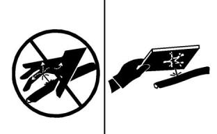
Always use a board or cardboard when you check for
a leak. Leaking fluid that is under pressure can
penetrate body tissue. Fluid penetration can cause
serious injury and possible death. A pin hole leak can
cause severe injury. If fluid is injected into your skin,
you must get treatment immediately. Seek treatment
from a doctor that is familiar with this type of injury.
When pressurized air and/or pressurized water is
used for cleaning, wear protective clothing, protective
shoes, and eye protection. Eye protection includes
goggles or a protective face shield.
The maximum air pressure for cleaning purposes
must be below 205 kPa (30 psi). The maximum water
pressure for cleaning purposes must be below
275 kPa (40 psi).
Containing Fluid Spillage
Care must be taken to ensure that fluids are
contained during performance of inspection,
maintenance, testing, adjusting, and repair of the
product. Be prepared to collect the fluid with suitable
containers before opening any compartment or
disassembling any component containing fluids.
Fluid Penetration
Pressure can be trapped in the hydraulic circuit long
after the engine has been stopped. The pressure can
cause hydraulic fluid or items such as pipe plugs to
escape rapidly if the pressure is not relieved correctly.
Dispose of all fluids according to local regulations and
mandates.
Do not remove any hydraulic components or parts
until pressure has been relieved or personal injury
may occur. Do not disassemble any hydraulic
components or parts until pressure has been relieved
or personal injury may occur. Refer to the OEM
information for any procedures that are required to
relieve the hydraulic pressure.
Static Electricity Hazard when
Fueling with Ultra-low Sulfur Diesel
Fuel
The removal of sulfur and other compounds in ultra-
low sulfur diesel fuel (ULSD fuel) decreases the
conductivity of ULSD and increases the ability of
ULSD to store static charge. Refineries may have
treated the fuel with a static dissipating additive.
Many factors can reduce the effectiveness of the
additive over time. Static charges can build up in
ULSD fuel while the fuel is flowing through fuel
delivery systems. Static electricity discharge when
combustible vapors are present could result in a fire
or explosion. Ensure that the entire system used to
refuel your machine (fuel supply tank, transfer pump,
transfer hose, nozzle, and others) is properly
grounded and bonded. Consult with your fuel or fuel
system supplier to ensure that the delivery system
complies with fueling standards for proper grounding
and bonding.
This document has been printed from SPI2. NOT FOR RESALE
![]()
![]()
![]()
SEBU9072
9
Safety Section
General Hazard Information
• Never use compressed air for cleaning.
• Avoid brushing materials that contain asbestos.
• Avoid grinding materials that contain asbestos.
Avoid static electricity risk when fueling. Ultra-low
sulfur diesel fuel (ULSD fuel) poses a greater stat-
ic ignition hazard than earlier diesel formulations
with a higher sulfur contents. Avoid death or seri-
ous injury from fire or explosion. Consult with
your fuel or fuel system supplier to ensure the de-
livery system is in compliance with fueling stand-
ards for proper grounding and bonding practices.
• Use a wet method in order to clean up asbestos
materials.
• A vacuum cleaner that is equipped with a high
efficiency particulate air filter (HEPA) can also be
used.
Inhalation
• Use exhaust ventilation on permanent machining
jobs.
• Wear an approved respirator if there is no other
way to control the dust.
• Comply with applicable rules and regulations for
the work place. In the United States, use
Occupational Safety and Health Administration
(OSHA) requirements. These OSHA requirements
can be found in “29 CFR 1910.1001”.
• Obey environmental regulations for the disposal of
asbestos.
• Stay away from areas that might have asbestos
particles in the air.
Dispose of Waste Properly
Illustration 6
g00702022
Exhaust
Use caution. Exhaust fumes can be hazardous to
health. If you operate the equipment in an enclosed
area, adequate ventilation is necessary.
Asbestos Information
Perkins equipment and replacement parts that are
shipped from Perkins engine company limited are
asbestos free. Perkins recommends the use of only
genuine Perkins replacement parts. Use the following
guidelines when you handle any replacement parts
that contain asbestos or when you handle asbestos
debris.
Illustration 7
g00706404
Use caution. Avoid inhaling dust that might be
generated when you handle components that contain
asbestos fibers. Inhaling this dust can be hazardous
to your health. The components that may contain
asbestos fibers are brake pads, brake bands, lining
material, clutch plates, and some gaskets. The
asbestos that is used in these components is usually
bound in a resin or sealed in some way. Normal
handling is not hazardous unless airborne dust that
contains asbestos is generated.
Improperly disposing of waste can threaten the
environment. Potentially harmful fluids should be
disposed of according to local regulations.
Always use leakproof containers when you drain
fluids. Do not pour waste onto the ground, down a
drain, or into any source of water.
If dust that may contain asbestos is present, there are
several guidelines that should be followed:
This document has been printed from SPI2. NOT FOR RESALE
![]()
![]()
![]()
![]()
![]()
![]()
![]()
10
SEBU9072
Safety Section
Burn Prevention
i06106969
i05945996
Fire Prevention and Explosion
Prevention
Burn Prevention
Coolant
When the engine is at operating temperature, the
engine coolant is hot. The coolant is also under
pressure. The radiator and all lines to the heaters or
to the engine contain hot coolant. Any contact with
hot coolant or with steam can cause severe burns.
Allow cooling system components to cool before the
cooling system is drained.
Check that the coolant level after the engine has
stopped and the engine has been allowed to cool.
Ensure that the filler cap is cool before removing the
filler cap. The filler cap must be cool enough to touch
with a bare hand. Remove the filler cap slowly in
order to relieve pressure.
Cooling system conditioner contains alkali. Alkali can
cause personal injury. Do not allow alkali to contact
the skin, the eyes, or the mouth.
Illustration 8
g00704000
All fuels, most lubricants, and some coolant mixtures
are flammable.
Oils
Flammable fluids that are leaking or spilled onto hot
surfaces or onto electrical components can cause a
fire. Fire may cause personal injury and property
damage.
Skin may be irritated following repeated or prolonged
exposure to mineral and synthetic base oils. Refer to
your suppliers Material Safety Data Sheets for
detailed information. Hot oil and lubricating
components can cause personal injury. Do not allow
hot oil to contact the skin. Appropriate personal
protective equipment should be used.
After the emergency stop button is operated, ensure
that you allow 15 minutes, before the engine covers
are removed.
Diesel Fuel
Determine whether the engine will be operated in an
environment that allows combustible gases to be
drawn into the air inlet system. These gases could
cause the engine to overspeed. Personal injury,
property damage, or engine damage could result.
Diesel may be irritating to the eyes, respiratory
system, and skin. Prolonged exposure to diesel may
cause various skin conditions. Appropriate personal
protective equipment should be used. Refer to
supplier Material safety Data sheets for detailed
information.
If the application involves the presence of
combustible gases, consult your Perkins dealer and/
or your Perkins distributor for additional information
about suitable protection devices.
Batteries
The liquid in a battery is an electrolyte. Electrolyte is
an acid that can cause personal injury. Do not allow
electrolyte to contact the skin or the eyes.
Remove all flammable combustible materials or
conductive materials such as fuel, oil, and debris from
the engine. Do not allow any flammable combustible
materials or conductive materials to accumulate on
the engine.
Do not smoke while checking the battery electrolyte
levels. Batteries give off flammable fumes which can
explode.
Store fuels and lubricants in correctly marked
containers away from unauthorized persons. Store
oily rags and any flammable materials in protective
containers. Do not smoke in areas that are used for
storing flammable materials.
Always wear protective glasses when you work with
batteries. Wash hands after touching batteries. The
use of gloves is recommended.
Do not expose the engine to any flame.
Exhaust shields (if equipped) protect hot exhaust
components from oil or fuel spray in case of a line, a
tube, or a seal failure. Exhaust shields must be
installed correctly.
This document has been printed from SPI2. NOT FOR RESALE
![]()
![]()
![]()
SEBU9072
11
Safety Section
Fire Prevention and Explosion Prevention
Do not weld on lines or tanks that contain flammable
fluids. Do not flame cut lines or tanks that contain
flammable fluid. Clean any such lines or tanks
thoroughly with a nonflammable solvent prior to
welding or flame cutting.
Avoid static electricity risk when fueling. Ultra-low
Sulfur Diesel fuel (ULSD fuel) poses a greater static
ignition hazard than earlier diesel formulations with a
higher sulfur content. Avoid death or serious injury
from fire or explosion. Consult your fuel or fuel system
supplier to ensure that the delivery system is in
compliance with fueling standards for proper
grounding and bonding practices.
Wiring must be kept in good condition. Ensure that all
electrical wires are correctly installed and securely
attached. Check all electrical wires daily. Repair any
wires that are loose or frayed before you operate the
engine. Clean all electrical connections and tighten all
electrical connections.
Eliminate all wiring that is unattached or unnecessary.
Do not use any wires or cables that are smaller than
the recommended gauge. Do not bypass any fuses
and/or circuit breakers.
Arcing or sparking could cause a fire. Secure
connections, recommended wiring, and correctly
maintained battery cables will help to prevent arcing
or sparking.
Ensure that the engine is stopped. Inspect all lines
and hoses for wear or for deterioration. Ensure that
the hoses are correctly routed. The lines and hoses
must have adequate support and secure clamps.
Oil filters and fuel filters must be installed correctly.
The filter housings must be tightened to the correct
torque. Refer to the Disassembly and Assembly
manual for more information.
Illustration 10
g00704135
Gases from a battery can explode. Keep any open
flames or sparks away from the top of a battery. Do
not smoke in battery charging areas.
Never check the battery charge by placing a metal
object across the terminal posts. Use a voltmeter or a
hydrometer.
Incorrect jumper cable connections can cause an
explosion that can result in injury. Refer to the
Operation Section of this manual for specific
instructions.
Do not charge a frozen battery. A frozen battery may
cause an explosion.
The batteries must be kept clean. The covers (if
equipped) must be kept on the cells. Use the
recommended cables, connections, and battery box
covers when the engine is operated.
Fire Extinguisher
Illustration 9
g00704059
Make sure that a fire extinguisher is available. Be
familiar with the operation of the fire extinguisher.
Inspect the fire extinguisher and service the fire
extinguisher regularly. Obey the recommendations on
the instruction plate.
Use caution when you are refueling an engine. Do not
smoke while you are refueling an engine. Do not
refuel an engine near open flames or sparks. Always
stop the engine before refueling.
Ether
Ether is flammable and poisonous.
This document has been printed from SPI2. NOT FOR RESALE
![]()
![]()
![]()
![]()
![]()
12
SEBU9072
Safety Section
Crushing Prevention and Cutting Prevention
Do not smoke while you are replacing an ether
cylinder or while you are using an ether spray.
Chips or other debris may fly off objects when objects
are struck. Before objects are struck, ensure that no
one will be injured by flying debris.
Do not store ether cylinders in living areas or in the
engine compartment. Do not store ether cylinders in
direct sunlight or in temperatures above 49° C
(120° F). Keep ether cylinders away from open
flames or sparks.
i05875651
Mounting and Dismounting
Lines, Tubes, and Hoses
Do not climb on the engine. The engine has not been
designed with mounting or dismounting locations.
Do not bend high-pressure lines. Do not strike high-
pressure lines. Do not install any lines that are
damaged.
Refer to the OEM for the location of foot and hand
holds for your specific application.
Leaks can cause fires. Consult your Perkins dealer or
your Perkins distributor for replacement parts.
i04257031
Replace the parts if any of the following conditions
are present:
Before Starting Engine
• End fittings are damaged or leaking.
• Outer coverings are chafed or cut.
• Wires are exposed.
NOTICE
For initial start-up of a new or rebuilt engine, and for
start-up of an engine that has been serviced, make
provision to shut the engine off should an overspeed
occur. This may be accomplished by shutting off the
air and/or fuel supply to the engine.
• Outer coverings are ballooning.
• Flexible parts of the hoses are kinked.
• Outer covers have embedded armoring.
• End fittings are displaced.
Make sure that all clamps, guards, and heat shields
are installed correctly. During engine operation,
correct installation will help to prevent vibration,
rubbing against other parts, and excessive heat.
Engine exhaust contains products of combustion
which may be harmful to your health. Always start
and operate the engine in a well ventilated area
and, if in an enclosed area, vent the exhaust to the
outside.
i02143194
Crushing Prevention and
Cutting Prevention
Inspect the engine for potential hazards.
Do not start the engine or move any of the controls if
there is a “DO NOT OPERATE” warning tag or
similar warning tag attached to the start switch or to
the controls.
Support the component correctly when work beneath
the component is performed.
Before starting the engine, ensure that no one is on,
underneath, or close to the engine. Ensure that the
area is free of personnel.
Unless other maintenance instructions are provided,
never attempt adjustments while the engine is
running.
If equipped, ensure that the lighting system for the
engine is suitable for the conditions. Ensure that all
lights work properly, if equipped.
Stay clear of all rotating parts and of all moving parts.
Leave the guards in place until maintenance is
performed. After the maintenance is performed,
reinstall the guards.
All protective guards and all protective covers must
be installed if the engine must be started in order to
perform service procedures. To help prevent an
accident that is caused by parts in rotation, work
around the parts carefully.
Keep objects away from moving fan blades. The fan
blades will throw objects or cut objects.
When objects are struck, wear protective glasses in
order to avoid injury to the eyes.
Do not start an engine when the governor linkage is
disconnected.
This document has been printed from SPI2. NOT FOR RESALE
![]()
![]()
![]()
![]()
![]()
SEBU9072
13
Safety Section
Engine Starting
Do not bypass the automatic shutoff circuits. Do not
disable the automatic shutoff circuits. The circuits are
provided in order to help prevent personal injury. The
circuits are also provided in order to help prevent
engine damage.
i01462046
Engine Stopping
Stop the engine according to the procedure in the
Operation and Maintenance Manual, “Engine
Stopping (Operation Section)” in order to avoid
overheating of the engine and accelerated wear of
the engine components.
i02583384
Engine Starting
Use the Emergency Stop Button (if equipped) ONLY
in an emergency situation. Do not use the Emergency
Stop Button for normal engine stopping. After an
emergency stop, DO NOTstart the engine until the
problem that caused the emergency stop has been
corrected.
Do not use aerosol types of starting aids such as
ether. Such use could result in an explosion and
personal injury.
Stop the engine if an overspeed condition occurs
during the initial start-up of a new engine or an engine
that has been overhauled. This may be accomplished
by shutting off the fuel supply to the engine and/or
shutting off the air supply to the engine.
If a warning tag is attached to the engine start switch
or to the controls DO NOTstart the engine or move
the controls. Consult with the person that attached
the warning tag before the engine is started.
To stop an electronically controlled engine, cut the
power to the engine.
All protective guards and all protective covers must
be installed if the engine must be started in order to
perform service procedures. To help prevent an
accident that is caused by parts in rotation, work
around the parts carefully.
i06088340
Electrical System
Start the engine from the operator's compartment or
from the engine start switch.
Always start the engine according to the procedure
that is described in the Operation and Maintenance
Manual, “Engine Starting” topic in the Operation
Section. Knowing the correct procedure will help to
prevent major damage to the engine components.
Knowing the procedure will also help to prevent
personal injury.
Never disconnect any charging unit circuit or battery
circuit cable from the battery when the charging unit is
operating. A spark can cause the combustible gases
that are produced by some batteries to ignite.
To help prevent sparks from igniting combustible
gases that are produced by some batteries, the
negative “−” jump-start cable should be connected
last from the external power source to the negative
“−” terminal of the starting motor. If the starting motor
is not equipped with a negative “−” terminal, connect
the jump-start cable to the engine block.
To ensure that the jacket water heater (if equipped) is
working correctly, check the water temperature gauge
and/or the oil temperature gauge during the heater
operation.
Engine exhaust contains products of combustion
which can be harmful to your health. Always start the
engine and operate the engine in a well ventilated
area. If the engine is started in an enclosed area, vent
the engine exhaust to the outside.
Check the electrical wires daily for wires that are
loose or frayed. Tighten all loose electrical wires
before the engine is started. Repair all frayed
electrical wires before the engine is started. Refer to
the “Engine Starting” section of this Operation and
Maintenance Manual for specific starting instructions.
Note: The engine may be equipped with a device for
cold starting. If the engine will be operated in very
cold conditions, then an extra cold starting aid may be
required. Normally, the engine will be equipped with
the correct type of starting aid for your region of
operation.
Grounding Practices
Proper grounding for the engine electrical system is
necessary for optimum engine performance and
reliability. Improper grounding will result in
uncontrolled electrical circuit paths and in unreliable
electrical circuit paths.
Uncontrolled electrical circuit paths can result in
damage to main bearings, to crankshaft bearing
journal surfaces, and to aluminum components.
This document has been printed from SPI2. NOT FOR RESALE
![]()
![]()
![]()
14
SEBU9072
Safety Section
Engine Electronics
Engines that are installed without engine-to-frame
ground straps can be damaged by electrical
discharge.
The Engine Monitoring package can vary for different
engine models and different engine applications.
However, the monitoring system and the engine
monitoring control will be similar for all engines.
To ensure that the engine and the engine electrical
systems function properly, an engine-to-frame ground
strap with a direct path to the battery must be used.
This path may be provided by way of a starting motor
ground, a starting motor ground to the frame, or a
direct engine ground to the frame.
Note: Many of the engine control systems and
display modules that are available for Perkins
Engines will work in unison with the Engine
Monitoring System. Together, the two controls will
provide the engine monitoring function for the specific
engine application. Refer to the Troubleshooting
Manual for more information.
All grounds should be tight and free of corrosion. The
engine alternator must be grounded to the negative
“-” battery terminal with a wire that is adequate to
handle the full charging current of the alternator.
i06091234
Engine Electronics
Tampering with the electronic system installation
or the OEM wiring installation can be dangerous
and could result in personal injury or death and/or
engine damage.
This engine has a comprehensive, programmable
Engine Monitoring System. The Engine Control
Module (ECM) will monitor the engine operating
conditions. If any of the engine parameters extend
outside an allowable range, the ECM will initiate an
immediate action.
The following actions are available for engine
monitoring control: WARNING, DERATE and
SHUTDOWN. These engine monitoring modes can
limit engine speed and/or the engine power.
Many of the parameters that are monitored by the
ECM can be programmed for the engine monitoring
functions. The following parameters can be monitored
as a part of the Engine Monitoring System:
• Operating Altitude
• Engine Coolant Level
• Engine Coolant Temperature
• Engine Oil Pressure
• Engine Speed
• Fuel Temperature
• Intake Manifold Air Temperature
• System Voltage
This document has been printed from SPI2. NOT FOR RESALE
![]()
![]()
![]()
SEBU9072
15
Product Information Section
Model View Illustrations
Product Information
Section
General Information
i06107001
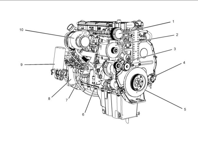
Model View Illustrations
The following model views show typical features of
the engine. Due to individual applications, your
engine may appear different from the illustrations.
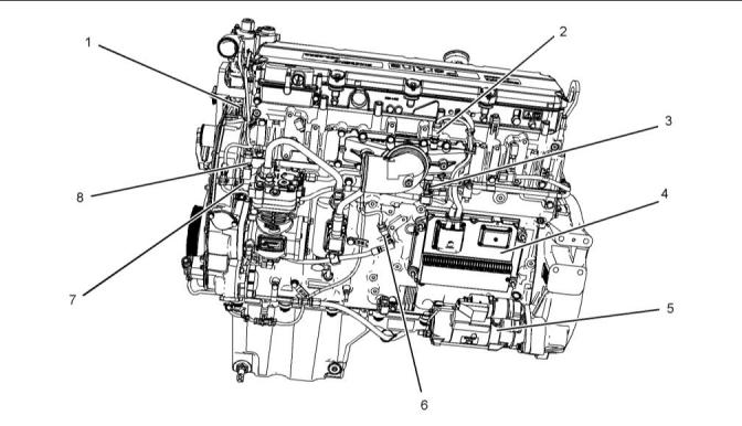
Illustration 11
g03812155
(1) Refrigerant compressor
(2) Alternator
(3) Belt tensioner
(5) Crankshaft damper
(6) Coolant intake
(7) Oil cooler
(9) Engine oil filter
(10) Turbocharger
(4) Fuel transfer pump
(8) Secondary fuel filter
This document has been printed from SPI2. NOT FOR RESALE
![]()
![]()
16
SEBU9072
General Information
Product Description
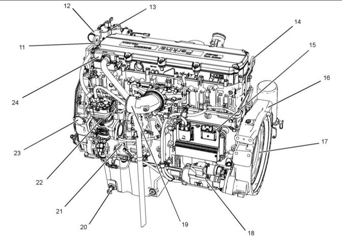
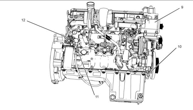
Illustration 12
g03812156
(11) Engine front lifting eye
(12) Coolant outlet
(16) Flywheel housing
(17) Flywheel
(21) Oil gauge (dipstick)
(22) Air compressor
(13) Water temperatureregulator housing
(14) Engine rear lifting eye
(15) Electronic control module
(18) Starting motor
(19) Air intake
(20) Oil drain valve
(23) Location for oil filler
(24) Engine crankcase breather
i06109638
Engine Specifications
Product Description
Note: The front end of the engine is opposite the
flywheel end of the engine. The left and the right
sides of the engine are determined from the flywheel
end. The number 1 cylinder is the front cylinder.
The Perkins 2206D-E13TA Industrial Engine have
the following characteristics:
• Four-stroke cycle
• Mechanically actuated, electronically controlled
fuel injection system
• Turbocharged
• Air to air charged cooled
This document has been printed from SPI2. NOT FOR RESALE
![]()
![]()
SEBU9072
17
General Information
Product Description
Additional Features
The following additional features provide increased
engine fuel economy and serviceability:
• Cold starting capability
• Tampering detection
• Diagnostics
Engine Service Life
Engine efficiency and maximum utilization of engine
performance depend on the adherence to proper
operation and maintenance recommendations. In
addition, use recommended fuels, coolants, and
lubricants. Use the Operation and Maintenance
Manual as a guide for required engine maintenance.
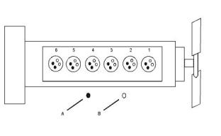
Illustration 13
g01387009
Cylinder and valve location
(A) Exhaust valve
(B) Inlet valv, e
Expected engine life is predicted by the average
power that is demanded. The average power that is
demanded is based on fuel consumption of the
engine over a time. Reduced hours of operation at full
throttle and/or operating at reduced throttle settings
result in a lower average power demand. Reduced
hours of operation will increase the length of
operating time before an engine overhaul is required.
For more information, refer to the Operation and
Maintenance Manual, “Overhaul Considerations”
topic.
Table 1
Engine Specifications
Engine
Arrangement and Cylinders
Bore
2206D
In-Line 6 cylinder
130 mm (5.1 inch)
Stroke
157 mm (6.2 inch)
ATAAC(1)
Aspiration
Aftermarket Products and Perkins
Engines
Displacement
12.5 L (763 cubic inch)
1-5-3-6-2-4
Perkins does not warrant the quality or performance
of non-Perkins fluids and filters.
Firing Order
Rotation (flywheel end)
Counterclockwise
When auxiliary devices, accessories, or consumables
(filters, additives, catalysts, ) which are made by other
manufacturers are used on Perkins products, the
Perkins warranty is not affected simply because of
such use.
(1)
Air-to-air aftercooled
Electronic Engine Features
However, failures that result from the installation
or use of other manufacturers devices,
accessories, or consumables are NOT Perkins
defects. Therefore, the defects are NOTcovered
under the Perkins warranty.
The engine is designed for electronic controls. The
integral on board computer controls the operation of
the engine. Current operating conditions are
monitored. The Electronic Control Module (ECM)
controls the response of the engine to these
conditions and to the demands of the operator. These
conditions and operator demands determine the
precise control of fuel injection by the ECM. The
electronic engine control system provides the
following features:
• Engine speed governor
• Automatic air/fuel ratio control
• Torque rise shaping
• Injection timing control
• System diagnostics
This document has been printed from SPI2. NOT FOR RESALE
![]()
![]()
![]()
18
SEBU9072
Product Identification Information
Plate Locations and Film Locations
Product Identification
Information
i06109784
Plate Locations and Film
Locations
Illustration 15
g01403841
Serial number plate
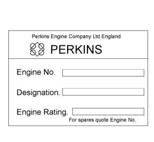
The following information is stamped on the serial
number plate: engine serial number, engine model
and arrangement number.
The engine information plate is located on top of the
valve cover near the middle of the engine.
The following information is on the information plate:
engine serial number, engine model, engine
arrangement number, maximum altitude of the engine
that is necessary to achieve the rated power,
horsepower, high idle, full load rpm, fuel settings and
other information
i05951816
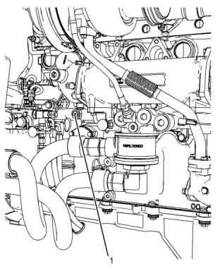
Emissions CertificationFilm
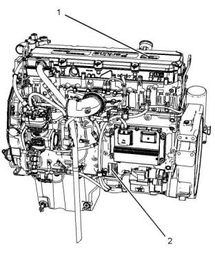
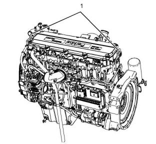
Illustration 14
g03812733
Typical example
(1) Information plate
(2) Serial number plate
Note: This information is pertinent in the United
States, in Canada and in Europe.
The engine serial number plate is located on the left
side of the engine block.
The emissions label is located on the top of the valve
mechanism cover.
i06109817
Reference Information
Information for the following items may be needed to
order parts. Locate the information for your engine.
Record the information in the appropriate space.
Make a copy of this list for a record. Keep the
information for future reference.
This document has been printed from SPI2. NOT FOR RESALE
![]()
![]()
![]()
![]()
![]()
SEBU9072
19
Product Identification Information
Reference Information
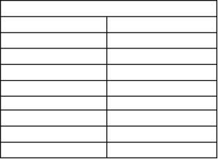
Record for Reference
Engine Model
Engine Serial number
Engine Low Idle rpm
Engine Full Load rpm
Primary Fuel Filter Element
Secondary Fuel Filters
Lubrication Oil Filter
Breather Fume Filter Element
Auxiliary Oil Filter
Total Lubrication System Capacity
Total Cooling System Capacity
Air Cleaner Element
Drive Belt
This document has been printed from SPI2. NOT FOR RESALE
![]()
![]()
![]()
![]()
![]()
![]()
![]()
![]()
![]()
![]()
![]()
![]()
![]()
20
SEBU9072
Operation Section
Product Lifting
Operation Section
Lifting and Storage
i06109969
Product Storage
Your Perkins distributor can assist in preparing the
engine for extended storage periods.
i06109876
Product Lifting
An engine can be stored for up to 6 months provided
all the recommendation are adhered to.
Engine
NOTICE
1. Clean the engine of any dirt, rust, grease, and oil.
Inspect the exterior. Paint areas that contain paint
damage with a good quality paint.
Never bend the eyebolts and the brackets. Only load
the eyebolts and the brackets under tension. Remem-
ber that the capacity of an eyebolt is less as the angle
between the supporting members and the object be-
comes less than 90 degrees.
2. Remove dirt from the air cleaners. Check all seals,
gaskets, and the filter element for damage.
When it is necessary to remove a component at an
angle, only use a link bracket that is properly rated for
the weight.
3. Apply lubricant to all points in this Operation and
Maintenance Manual, “Maintenance Interval
Schedule”.
Read all the information within produce lifting before
any lifting is attempted. Ensure that the correct set of
lifting eyes for the assembly to be lifted have been
selected.
4. Drain the crankcase oil. Replace the crankcase oil
and change the oil filters. For the proper
procedure, refer to this Operation and
Maintenance Manual.
Use a hoist to remove heavy components. Use an
adjustable lifting beam to lift the assembly. All
supporting members (chains and cables) should be
parallel to each other. The chains and cables should
be perpendicular to the top of the object that is being
lifted.
5. Add VCI oil to the crankcase oil. The volume of VCI
oil in the crankcase oil should be 3 to 4 percent.
Note: If the engine crankcase is full, drain enough
engine oil so the mixture can be added.
6. Remove the air filter elements. Turn the engine at
cranking speed with the throttle control in FUEL
OFF position. Use a sprayer to add a mixture of 50
percent VCI oil and 50 percent engine oil into the
air inlet or turbocharger inlet.
Note: The mixture of VCI oil can be added to the inlet
by removing the plug for checking turbocharger boost
pressure. The minimum application rate for the VCI
oil mixture is 5.5 mL per L (3 oz per 1000 cu in) of
engine displacement.
7. Use a sprayer to apply a mixture of 50 percent VCI
oil and 50 percent crankcase oil into the exhaust
openings. The minimum application rate for the oil
mixture is 5.5 mL per L (3 oz per 1000 cu in) of
engine displacement. Seal the exhaust pipe and
seal any drain holes in the muffler.
8. Remove the fuel from the secondary fuel filter
housing. Alternately, empty and reinstall the spin-
on fuel filter element in order to remove any dirt
and water. Drain any sleeve metering fuel pump.
Illustration 16
g03812766
(1) Engine lifting eyes
This document has been printed from SPI2. NOT FOR RESALE
![]()
![]()
![]()
![]()
![]()
SEBU9072
21
Lifting and Storage
Product Storage
Clean the primary fuel filter. Fill with calibration
fluid or kerosene. Install the primary fuel filter and
operate the priming pump. This procedure will
send clean oil to the secondary filter and the
engine.
13. Remove the drive belts from the engine
14. Place a waterproof cover over the engine. Ensure
that the engine cover is secure. The cover should
be loose enough to allow air to circulate around the
engine in order to prevent damage from
condensation.
Open the fuel tank drain valve in order to drain any
water and dirt from the fuel tank. Apply a spray of
calibration fluid or kerosene at the rate of
30 mL per 30 L (1 oz per 7.50 gal US) of fuel tank
capacity in order to prevent rust in the fuel tank.
Add 0.15 mL per L (.02 oz per 1 gal US) of
15. Attach a tag with the storage date to the engine.
16. Remove the waterproof cover at 2 month or 3
month intervals in order to check the engine for
corrosion. If the engine has signs of corrosion,
repeat the protection procedure.
commercial biocide such as Biobor JF to the fuel.
Apply a small amount of oil to the threads on the
fuel tank filler neck and install the cap. Seal all
openings to the tank in order to prevent
evaporation of the fuel and as a preservative.
Coolant System
9. Remove the fuel injectors. Apply 30 mL (1 oz) of
the mixture of oils (50 percent VCI oil and 50
percent engine oil) into each cylinder.
Completely fill the cooling system before storage.
Refer to this Operation and Maintenance Manual,
“Fluid Recommendations” for more information about
coolants.
Use a bar or a turning tool in order to turn over the
engine slowly. This procedure puts the oil on the
cylinder walls. Install all fuel injectors and tighten to
the correct torque. Refer to Disassembly and
Assembly Manual for more information.
Remove Engine from Storage
1. Remove all outside protective covers.
2. Change the oil and filters.
10. Spray a thin amount of a mixture of 50 percent
VCI oil and 50 percent engine oil onto the following
components: flywheel, ring gear teeth and starter
pinion. Install the covers in order to prevent
evaporation of the vapors from the VCI oil.
3. Check the condition of the fan and alternator belts.
Replace the belts, if necessary. Refer to this
Operation and Maintenance Manual, “Belts -
Inspect/Adjust/Replace” for the correct procedure.
11. Apply a heavy amount of Multipurpose Grease to
all outside parts that move, such as rod threads,
ball joints, linkage.
4. Replace the fuel filter elements.
5. Remove the plastic covers from the air cleaner
elements.
Note: Install all covers. Ensure that tape has been
installed over all openings, air inlets, exhaust
openings, the flywheel housing, the crankcase
breathers, the dipstick tubes.
6. Use a bar or a turning tool in order to turn the
engine in the normal direction of rotation. The
procedure ensures that no hydraulic locks or
resistance exist.
Ensure that all covers are airtight and
weatherproof. Use a waterproof weather resistant
tape such as Kendall No. 231 or an equivalent.
Do not use duct tape. Duct tape will only seal for a
short time.
7. Before starting the engine, remove the valve cover
or covers. Put a large amount of engine oil on the
camshaft, cam followers, and valve mechanism in
order to prevent damage to the mechanism.
12. Under most conditions, removing the batteries is
the best procedure. As an alternative, place the
batteries in storage. As needed, periodically
charge the batteries while the batteries are in
storage.
If the batteries are not removed, wash the tops of
the batteries until the tops are clean. Apply an
electrical charge to the batteries in order to obtain
a specific gravity of 1.225.
Disconnect the battery terminals. Place a plastic
cover over the batteries.
This document has been printed from SPI2. NOT FOR RESALE
![]()
22
SEBU9072
Lifting and Storage
Product Storage
10. Before start-up, test the cooling system for a 3
percent to a 6 percent concentration of coolant
conditioner. Add liquid coolant conditioner or a
coolant conditioner element, if equipped.
Test the coolant mixture for proper nitrite level. If
necessary, adjust the coolant mixture.
Prime the engine with clean diesel fuel before
starting.
11. Ensure that the cooling system is clean. Ensure
that the system is full. Ensure that the system has
the correct amount of supplemental cooling system
conditioner.
12. On the first day of operation, check the entire
engine several times for leaks and correct
operation.
Illustration 17
g03862125
Typical example
(1) plug
8. If an engine is stored for more than 1 year, Perkins
recommends Pre lubrication of the engine in order
to avoid dry starting. Use a suitable pump in order
to put engine oil into the engine oil system.
The pump will need to create a minimum pressure
within the engine of 0.25 bar (3.6 psi). This
pressure is needed for 15 seconds in order to
lubricate the internal surfaces.
Remove of the plug shown in illustration 17 in
order to connect to the engine oil system. The
connection required is 9/16" x 18 tpi. Ensure that
the correct oil specification is used, refer to this
Operation and Maintenance Manual, “Fluid
Recommendations” for more information. After the
engine internal surfaces have been lubricated,
remove connector and install plug (1). Tighten plug
to a torque of 30 N·m (265 lb in). Perkins
recommends that the procedure must be
performed in a minimum ambient temperature of
10° C (50° F).
9. Check the condition of all rubber hoses. Replace
any worn hoses. Replace any damaged hoses.
This document has been printed from SPI2. NOT FOR RESALE
![]()
![]()
![]()
SEBU9072
23
Features and Controls
Battery Disconnect Switch
Features and Controls
The battery disconnect switch and the engine start
switch perform different functions. The entire
electrical system is disabled when you turn the
battery disconnect switch to the OFF position. The
battery remains connected to the electrical system
when you turn the engine start switch to the OFF
position.
i05422613
Battery Disconnect Switch
(If Equipped)
Turn the battery disconnect switch to the OFF
position and remove the key when you service the
electrical system or any other engine components.
Turn the battery disconnect switch to the OFF
position and remove the disconnect switch key after
you operate the engine. This will prevent the battery
from being discharged. The following problems can
cause battery discharge:
• short circuits
• current draw via some components
• vandalism
i06119742
MonitoringSystem
Illustration 18
g03422039
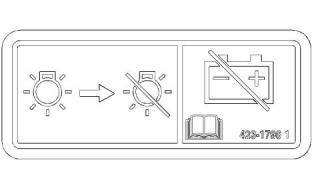
NOTICE
The monitoring system is designed to alert the
operator to an immediate problem.
Do not turn off the battery disconnect switch until the
indicator lamp has turned off. If the switch is turned off
when the indicator lamp is illuminated the Diesel Ex-
haust Fluid (DEF) system will not purge the DEF. If
the DEF does not purge, DEF could freeze and dam-
age the pump and lines.
The engine has protection in three stages:
• Warning
• Action Alert
• Shutdown
NOTICE
Never move the battery disconnect switch to the OFF
position while the engine is operating. Serious dam-
age to the electrical system could result.
The engine protection may be overridden by the
critical condition mode.
The Electronic Control Module (ECM) monitors the
following parameters:
Battery Disconnect Switch – The battery
disconnect switch can be used in order
to disconnect the battery from the
engines electrical system. The key must be
inserted into the battery disconnect switch before
the battery disconnect switch can be turned.
• Engine Temperatures
• Engine Pressures
• Engine Speed
If the parameters exceed a trip point for a period that
is longer than the delay period, the ECM logs an
event code. The indicator switches to the ON
position.
ON – To activate the electrical system,
insert the disconnect switch key and
turn the battery disconnect switch
clockwise. The battery disconnect switch must be
turned to the ON position before you start the
engine.
The following parameters are monitored for event
codes:
OFF – To deactivate the electrical
system, turn the battery disconnect
switch counterclockwise to the OFF
position.
This document has been printed from SPI2. NOT FOR RESALE
![]()
![]()
![]()
![]()
![]()
![]()
![]()
![]()
![]()
![]()
24
SEBU9072
Features and Controls
Monitoring System
• Lubricating Oil Pressure
• Coolant Temperature
• Overspeed
Shutdown
If the engine reaches the Shutdown condition, one of
the following events has occurred: low lubricating oil
pressure, high coolant temperature, or overspeed.
The event will be logged in the memory of the ECM.
The engine will be shut down. An event code will be
transmitted over the Perkins Data link and the hard
wired Shutdown output will be energized. The
Shutdown condition will latch until the ECM is reset.
The event code for the shutdown cannot be cleared
from the memory of the ECM without using a factory
password.
• Intake Manifold Temperature
• Intake Manifold Pressure
• Fuel Temperature
The temperature protection is disabled for a period
when the engine is cranking in order to compensate
for heat soak solutions.
Critical Protection Override
The ECM has dedicated alarm outputs for each of the
three stages of protection. There are also dedicated
alarm outputs for oil pressure, coolant temperature,
and overspeed events which are energized at any
stage of protection.
If the engine is in an application that is critical for
safety, the protection system can be overridden in
order to ensure the continuation of the power supply
during engine fault conditions.
Critical Protection Override will be set by a switch
input from the OEM. For example, switch to battery +
in order to disable a critical override. Critical
Protection Override input can be enabled in the
electronic service tool by use of a factory password.
Warning Alarm
The Warning alarm informs the user that the engine is
approaching a critical condition.
When the Critical Protection Override feature is
active, the ECM will continue to run the engine in all
shutdown conditions except for Overspeed shutdown.
If the shutdown is overridden, an event code is
generated. The ECM will log the event code. The
ECM will energize the following: Warning, Action
Alert, Shutdown, oil pressure, coolant temperature
and overspeed outputs as normal. The warranty of
the engine will be invalidated if the engine is operated
in the following conditions: active event code and
Critical Protection Override mode.
If the engine is in the Warning condition, then the
event will be logged in the memory of the ECM. An
event code will be transmitted over the Perkins Data
link and the hard wired Warning output will be
energized. If the engine is in the Warning condition,
the event code and output will remain while the
condition exists. The electronic service tool is used to
remove the event code from the memory of the ECM.
The trip point for the Warning alarm will be set to a
factory default in production. The electronic service
tool may be used to alter the trip point for a Warning
within predefined limits.
Standard Warning Outputs
Action Alert
The ECM provides individual outputs in order to drive
warning lamps or relays to indicate each of the
following fault conditions:
The Action Alert informs the OEM that the engine is
approaching a critical condition. The engine should
be stopped in a controlled manner. Further running of
the engine may result in an immediate shutdown.
• Diagnostic Fault
• Oil Pressure
• Coolant Temperature
• Overspeed
If the engine is in the Action Alert condition, the event
will be logged in the memory of the ECM. An event
code will be transmitted over the Perkins Data link
and the hard wired Action Alert will be energized. If
the engine is in the Action Alert condition, the event
code and output will remain while the condition exists.
The event code cannot be cleared from the memory
of the ECM without using a factory password.
• Action Alert
• Warning
• Shutdown
If the ECM detects a warning for the coolant
temperature , the output on the coolant temperature
will be energized and the warning output will be
energized. If the ECM detects a warning for the low
oil pressure, the output on the oil pressure will be
energized and the warning output will be energized.
This document has been printed from SPI2. NOT FOR RESALE
![]()
SEBU9072
25
Features and Controls
Sensors and Electrical Components
If the Action Alert alarms are enabled and the ECM
detects a coolant temperature condition, the output
on the coolant Temperature will be energized and the
output on the Action Alert will be energized.
The Diagnostic output differs from the Warning and
Shutdown outputs. The Warning and Shutdown
outputs refer to the operation of the engine. The
Diagnostic output refers to the condition of the
electronic system and software system.
If the engine shuts down on low oil pressure the
output on the low oil pressure will be energized and
the output on the shutdown will be energized. If the
engine shuts down on coolant temperature, or the
engine shuts down on overspeed the dedicated
output and the shutdown output will be energized.
A diagnostic fault may develop on the lubricating oil
pressure or coolant temperature sensors. For
example, if a Shutdown protection sensor has a fault,
this will result in an engine shutdown, unless the
system is in critical protection override. If a diagnostic
fault occurs, with one of the engine speed sensors
while the engine is running. The engine continues to
run by using the other timing sensor for reference.
Shutdown Reset
The cause of an engine shutdown must be
investigated. Corrective action must be taken before
the system is reset in order to operate the engine.
i06137289
Sensors and Electrical
Components
After an engine shutdown, operate the reset input of
the ECM or power down the controller.
Powering down the electronic control module can be
achieved by the operation of the keyswitch into sleep
mode. The electronic control module can be powered
down by isolating the power supply to the electronic
control module.
The illustrations within the following sections are
typical location of the sensors or electrical
components for an industrial engine. Specific engines
may appear different due to differences in
applications.
Note: The ECM cannot be reset by using the Reset
input until the engine has stopped.
Diagnostic
If there is a fault with an engine protection sensor on
the engine, the engine activates a diagnostic code.
The engine communicates the diagnostic code to the
operator via the Diagnostic output. The diagnostic
code provides an indication to the operator of a fault
with the engine protection system. Running of the
engine for a prolonged period in this condition may
result in engine failure. The output is generally used
to drive lamps or relays.
The following sensors are monitored in order to
determine if the sensors are out of the normal range,
an open circuit, or a short circuit:
• Atmosphere Pressure
• Lubricating Oil Pressure
• Inlet Manifold Pressure
• Inlet Manifold Temperature
• Fuel Temperature
• Coolant Temperature
• Engine Speed
• Desired Speed Input
This document has been printed from SPI2. NOT FOR RESALE
![]()
26
SEBU9072
Features and Controls
Sensors and Electrical Components
Illustration 19
g03822008
(1) Coolant temperature sensor
(2) Inlet manifold pressure sensor
(3) Inlet air temperature sensor
(4) Electronic control module
(5) Starting motor
(6) Oil pressure sensor
(7) Camshaft speed timing sensor
(8) Barometric pressure sensor
This document has been printed from SPI2. NOT FOR RESALE
![]()
![]()
SEBU9072
27
Features and Controls
Sensors and Electrical Components
Illustration 20
g03822009
(9) Alternator
(10) Crankshaft speed timing sensor
(11) Fuel temperature sensor
(12) Fuel pressure sensor
This document has been printed from SPI2. NOT FOR RESALE
![]()
![]()
28
SEBU9072
Engine Diagnostics
Self-Diagnostics
Engine Diagnostics
i01902949
Fault Logging
i05194988
Self-Diagnostics
The system provides the capability of Fault Logging.
When the Electronic Control Module (ECM)
generates an active diagnostic code, the code will be
logged in the memory of the ECM. The codes that
have been logged by the ECM can be identified by
the electronic service tool. The active codes that have
been logged will be cleared when the fault has been
rectified or the fault is no longer active. The following
logged faults can not be cleared from the memory of
the ECM without using a factory password:
Perkins Electronic Engines have the capability to
perform a self-diagnostics test. When the system
detects an active problem, a diagnostic lamp is
activated. Diagnostic codes will be stored in
permanent memory in the Electronic Control Module
(ECM). The diagnostic codes can be retrieved by
using Perkins electronic service tools.
Overspeed, low engine oil pressure and high engine
coolant temperature.
Some installations have electronic displays that
provide direct readouts of the engine diagnostic
codes. Refer to the manual that is provided by the
OEM for more information on retrieving engine
diagnostic codes.
i03554534
Engine Operation with Active
Diagnostic Codes
Active codes represent problems that currently exist.
These problems should be investigated first.
Logged codes represent the following items:
• Intermittent problems
If a diagnostic lamp illuminates during normal engine
operation, the system has identified a situation that is
not within the specification. Use electronic service
tools to check the active diagnostic codes.
• Recorded events
• Performance history
Note: If the customer has selected “DERATE” and if
there is a low oil pressure condition, the Electronic
Control Module (ECM) will limit the engine power until
the problem is corrected. If the oil pressure is within
the normal range, the engine may be operated at the
rated speed and load. However, maintenance should
be performed as soon as possible.
The problems may have been repaired since the
logging of the code. These codes do not indicate that
a repair is needed. The codes are guides or signals
when a situation exists. Codes may be helpful to
troubleshoot problems.
When the problems have been corrected, the
corresponding logged fault codes should be cleared.
The active diagnostic code should be investigated.
The cause of the problem should be corrected as
soon as possible. If the cause of the active diagnostic
code is repaired and there is only one active
i03554520
diagnostic code, the diagnostic lamp will turn off.
Diagnostic Lamp
Operation of the engine and performance of the
engine can be limited as a result of the active
diagnostic code that is generated. Acceleration rates
may be significantly slower. Refer to the
Troubleshooting Guide for more information on the
relationship between these active diagnostic codes
and engine performance.
A diagnostic lamp is used to indicate the existence of
an active fault. A fault diagnostic code will remain
active until the problem is repaired. The diagnostic
code may be retrieved by using the electronic service
tool.
i06225055
Configuration Parameters
The engine electronic control module (ECM) has two
types of configuration parameters. The system
configuration parameters and the customer specified
parameters.
This document has been printed from SPI2. NOT FOR RESALE
![]()
SEBU9072
29
Engine Diagnostics
Engine Operation with Intermittent Diagnostic Codes
The electronic service tool is required in order to alter
the configuration parameters.
System ConfigurationParameters
System configuration parameters affect the emissions
of the engine or the power of the engine. System
configuration parameters are programmed at the
factory. Normally, system configuration parameters
would never require changing through the life of the
engine. System configuration parameters must be
reprogrammed if an ECM is replaced. System
configuration parameters do not require
reprogrammed if the ECM software is changed.
Factory passwords are required to change these
parameters.
For more information on system configuration
parameters and customer specified parameters, refer
to Troubleshooting manual.
i01797063
Engine Operation with
Intermittent Diagnostic Codes
If a diagnostic lamp illuminates during normal engine
operation and the diagnostic lamp shuts off, an
intermittent fault may have occurred. If a fault has
occurred, the fault will be logged into the memory of
the Electronic Control Module (ECM).
In most cases, it is not necessary to stop the engine
because of an intermittent code. However, the
operator should retrieve the logged fault codes and
the operator should reference the appropriate
information in order to identify the nature of the event.
The operator should log any observation that could
have caused the lamp to light.
• Low power
• Limits of the engine speed
• Excessive smoke, etc
This information can be useful to help troubleshoot
the situation. The information can also be used for
future reference. For more information on diagnostic
codes, refer to the Troubleshooting Guide for this
engine.
This document has been printed from SPI2. NOT FOR RESALE
![]()
30
SEBU9072
Engine Starting
Before Starting Engine
Engine Starting
• Do not start the engine or move any of the controls
if there is a “DO NOT OPERATE” warning tag or
similar warning tag attached to the start switch or
to the controls.
i02109067
Before Starting Engine
• Ensure that the areas around the rotating parts are
clear.
• All of the guards must be put in place. Check for
damaged guards or for missing guards. Repair any
damaged guards. Replace damaged guards and/
or missing guards.
Perform the required daily maintenance and other
periodic maintenance before the engine is started.
Inspect the engine compartment. This inspection can
help prevent major repairs at a later date. Refer to the
Operation and Maintenance Manual, “Maintenance
Interval Schedule” for more information.
• Disconnect any battery chargers that are not
protected against the high current drain that is
created when the electric starting motor (if
equipped) is engaged. Check electrical cables and
check the battery for poor connections and for
corrosion.
• For the maximum service life of the engine, make
a thorough inspection before the engine is started.
Look for the following items: oil leaks, coolant
leaks, loose bolts and trash buildup. Remove trash
buildup and arrange for repairs, as needed.
• Reset all of the shutoffs or alarm components.
• Inspect the aftercooler for loose connections and
for debris buildup.
• Check the engine lubrication oil level. Maintain the
oil level between the “ADD” mark and the “FULL”
mark on the oil level gauge.
• Inspect the cooling system hoses for cracks and
for loose clamps.
• Check the coolant level. Observe the coolant level
in the coolant recovery tank (if equipped). Maintain
the coolant level to the “FULL” mark on the
coolant recovery tank.
• Inspect the alternator and accessory drive belts for
cracks, breaks, and other damage.
• Inspect the wiring for loose connections and for
worn wires or frayed wires.
• If the engine is not equipped with a coolant
recovery tank maintain the coolant level within
13 mm (0.5 inch) of the bottom of the filler pipe. If
the engine is equipped with a sight glass, maintain
the coolant level in the sight glass.
• Check the fuel supply. Drain water from the water
separator (if equipped). Open the fuel supply
valve.
• Observe the air cleaner service indicator (if
equipped). Service the air cleaner when the yellow
diaphragm enters the red zone, or when the red
piston locks in the visible position.
NOTICE
All valves in the fuel return line must be open before
and during engine operation to help prevent high fuel
pressure. High fuel pressure may cause filter housing
failure or other damage.
• Ensure that any driven equipment has been
disengaged. Minimize electrical loads or remove
any electrical loads.
If the engine has not been started for several weeks,
fuel may have drained from the fuel system. Air may
have entered the filter housing. Also, when fuel filters
have been changed, some air pockets will be trapped
in the engine. In these instances, prime the fuel
system. Refer to the Operation and Maintenance
Manual, “Fuel System - Prime” for more information
on priming the fuel system.
i04132731
Cold Weather Starting
Startability will be improved at temperatures below
10°C (50°F) from the use of a cylinder block coolant
heater or from other means that are used to heat the
crankcase oil. Some engine applications use a jacket
water heater to improve startability. Use of a jacket
water heater will help reduce white smoke and misfire
during start-up in cold weather.
Engine exhaust contains products of combustion
which may be harmful to your health. Always start
and operate the engine in a well ventilated area
and, if in an enclosed area, vent the exhaust to the
outside.
This document has been printed from SPI2. NOT FOR RESALE
![]()
![]()
![]()
![]()
![]()
SEBU9072
31
Engine Starting
Starting the Engine
Note: If the engine has not been run for several
weeks, fuel may have drained. Air may have moved
into the filter housing. Also, when fuel filters have
been changed, some air will be left in the filter
housing. Refer to the Operation and Maintenance
Manual, “Fuel System - Prime” (Maintenance
Section) for more information on priming the fuel
system.
During the key on, all warning lamps will illuminate
for a few seconds, in order to test the circuits. If
any lamps do not illuminate, check the bulbs and
replace as necessary.
NOTICE
Do not engage the starting motor when flywheel is
turning. Do not start the engine under load.
Ether Injection System (If
Equipped)
If the engine fails to start within 30 seconds, release
the starter switch or button and wait two minutes to al-
low the starting motor to cool before attempting to
start the engine again.
The ether injection system is controlled by the ECM.
The ECM monitors the coolant temperature, intake air
temperature, ambient air temperature, and barometric
pressure to determine when ether injection is needed.
At sea level, ether will be used if any of the
temperatures fails to exceed 0° C (32° F). This
temperature is subject to an increase as barometric
pressure increases.
3. Push the start button or turn the ignition switch to
the START position in order to crank the engine.
Do not push down or hold the throttle down while
the engine is cranked. The system will
automatically provide the correct amount of fuel
that is needed to start the engine.
4. If the engine fails to start within 30 seconds,
release the start button, or the ignition switch. Wait
for 2 minutes in order to allow the starting motor to
cool before attempting to start the engine again.
Personal injury or property damage can result
from alcohol or starting fluids.
Alcohol or starting fluids are highly flammable
and toxic and if improperly stored could result in
injury or property damage.
NOTICE
Oil pressure should rise within 15 seconds after the
engine starts. Do not increase engine rpm until the oil
pressure gauge indicates normal. If oil pressure is not
indicated on the gauge within 15 seconds, DO NOT
operate the engine. STOP the engine, investigate
and correct the cause.
Follow the procedure in this Operation and
Maintenance Manual, “Starting the Engine”.
i06092648
Starting the Engine
5. Allow the engine to idle for approximately 3
minutes. Idle the engine until the water
temperature gauge has begun to rise. Check all
gauges during the warm-up period.
Engine exhaust contains products of combustion
which may be harmful to your health. Always start
and operate the engine in a well ventilated area
and, if in an enclosed area, vent the exhaust to the
outside.
Note: Oil pressures and fuel pressures should be in
the normal range on the instrument panel. Engines
that are equipped with “WARNING” lamps do not
have an operating range. The “WARNING and
DIAGNOSTIC” lamp (if equipped) will flash while the
engine is cranking. The lamp should turn off after
proper engine oil pressure or fuel pressure is
achieved. Do not apply a load to the engine or
increase engine rpm until the oil pressure gauge
indicates at least normal pressure. Inspect the engine
for leaks and/or unusual noises.
Starting the Engine
Refer to the Owners Manual of the OEM for your type
of controls. Use the following procedure to start the
engine.
1. Place the transmission in NEUTRAL. Disengage
the flywheel clutch in order to allow the engine to
start faster, and to reduce the draining of the
battery.
2. Turn the ignition switch to the ON position.
This document has been printed from SPI2. NOT FOR RESALE
![]()
![]()
![]()
![]()
![]()
![]()
![]()
![]()
![]()
32
SEBU9072
Engine Starting
Starting with Jump Start Cables
If the engine is operated with a low load, the engine
will reach normal operating temperature sooner than
idling the engine with no load. When the engine is
idled in cold weather, increase the engine rpm to
approximately 1000 to 1200 rpm in order to raise
engine temperature. Do not exceed the
recommended rpm in order to increase the speed of
the warm-up. Limit unnecessary idle time to 10
minutes.
2. If a wire is loose, push the wire back into the
connector. Pull the wire again in order to e, nsure
that the wire is secure.
3. Start the engine. If the engine does not start, check
for a diagnostic code and consult your Perkins
distributor.
i06092747
Starting Problems
Starting with Jump Start
Cables
An occasional starting problem may be caused by
one of the following items:
(Do Not Use This Procedure in
Hazardous Locations that have
Explosive Atmospheres)
• Low battery charge
• Lack of fuel
• Problem with the wiring harness
If the engine fuel system has been run dry, fill the fuel
tank and prime the fuel system. Refer to the
Operation and Maintenance Manual, “Fuel System -
Prime” topic (Maintenance Section).
The connection of battery cables to a battery and
the disconnection of battery cables from a battery
may cause an explosion which may result in in-
jury or death. The connection and the disconnec-
tion of other electrical equipment may also cause
an explosion which may result in injury or death.
The procedures for the connection and the dis-
connection of battery cables and other electrical
equipment should only be performed in a nonex-
plosive atmosphere.
If the other problems are suspected, perform the
appropriate procedure in order to start the engine.
Problems with the Wiring Harness
Improper jump start cable connections can cause
an explosion resulting in personal injury.
Prevent sparks near the batteries. Sparks could
cause vapors to explode. Do not allow jump start
cable ends to contact each other or the engine.
Note: If possible, first diagnose the reason for the
starting failure. Refer to Troubleshooting, “Engine Will
Not Crank and Engine Cranks But Will Not Start” for
further information. Make any necessary repairs. If
the engine will not start only due to the condition of
the battery, either charge the battery, or start the
engine by using another battery with jump-start
cables.
Illustration 21
g01248812
ECM Connector J2/P2
The condition of the battery can be rechecked after
the engine has been switched OFF.
Locate the ECM. Check the connector in order to
ensure that the connector is secure. Lightly pull each
of the wires in the chassis harness.
1. Pull each wire with approximately 4.5 kg (10 lb) of
force. The wire should remain in the connector.
This document has been printed from SPI2. NOT FOR RESALE
![]()
![]()
![]()
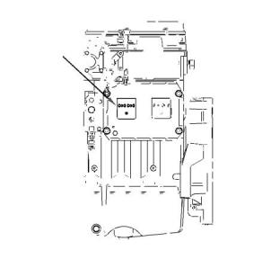
![]()
![]()
![]()
![]()
SEBU9072
33
Engine Starting
After Starting Engine
i05359363
NOTICE
Using a battery source with the same voltage as the
electric starting motor. Use ONLY equal voltage for
jump starting. The use of higher voltage will damage
the electrical system.
After Starting Engine
Note: In temperatures from 0 to 60°C (32 to 140°F),
the warm-up time is approximately 3 minutes. In
temperatures below 0°C (32°F), additional warm-up
time may be required.
Do not reverse the battery cables. The alternator can
be damaged. Attach ground cable last and remove
first.
Turn all electrical accessories OFF before attaching
the jump start cables.
When the engine is idling during warm-up, observe
the following conditions:
Ensure that the main power switch is in the OFF posi-
tion before attaching the jump start cables to the en-
gine being started.
• Check for fluid or air leaks at idle rpm and at one-
half full rpm (no load on the engine) before
operating the engine under load. Operating the
engine at idle and at one-half full rpm with no load
is not possible in some applications.
1. Turn the start switch on the stalled engine to the
OFF position. Turn off all the engines accessories.
• Operate the engine at low idle until all systems
achieve operating temperatures. Check all gauges
during the warm-up period.
2. Connect one positive end of the jump-start cable to
the positive cable terminal of the discharged
battery. Connect the other positive end of the jump-
start cable to the positive cable terminal of the
electrical source.
Note: Gauge readings should be observed and the
data should be recorded frequently while the engine
is operating. Comparing the data over time will help to
determine normal readings for each gauge.
Comparing data over time will also help detect
abnormal operating developments. Significant
changes in the readings should be investigated.
3. Connect one negative end of the jump-start cable
to the negative cable terminal of the electrical
source. Connect the other negative end of the
jump-start cable to the engine block or to the
chassis ground. This procedure helps to prevent
potential sparks from igniting the combustible
gases that are produced by some batteries.
Extended Idle at Cold Ambient
Temperature
The engine may automatically change speeds when
the engine is idling in cold ambient temperatures
(typically less than 0° C (32° F) for extended periods.
The purpose of the automatic speed change is
threefold: to maintain the desired operation of the
NOx reduction system, to maintain the desired
operation of the regeneration system and to keep the
engine coolant warm. The engine speed may rise to
1600 rpm for as long as 20 minutes.
Note: The engine ECM must be powered before the
starting motor is operated or damage can occur.
4. Start the engine in the normal operating procedure.
Refer to this Operation and Maintenance Manual,
“Starting the Engine”.
5. Immediately after the engine is started, disconnect
the jump-start cables in reverse order.
The high exhaust system temperature lamp may
illuminate during extended idling conditions. This
illumination signals that a diesel particulate filter
(DPF) regeneration is in progress. Regenerations
during cold ambient extended idling may only last up
to 10 minutes.
After jump starting, the alternator may not be able to
recharge fully batteries that are severely discharged.
The batteries must be replaced or charged to the
proper voltage with a battery charger after the engine
is stopped. Many batteries which are considered
unusable are still rechargeable. Refer to Operation
and Maintenance Manual, “Battery - Replace” and
Testing and Adjusting Manual, “Battery - Test”.
This document has been printed from SPI2. NOT FOR RESALE
免費熱線
400-100-8969???15088860848
400-100-8969???15088860848
機組銷售
0574-26871589? 15267810868
0574-26871589? 15267810868
配件銷售
0574-26886646? 15706865167
0574-26886646? 15706865167
維修熱線
0574-26871569 18658287286
0574-26871569 18658287286
手機端

微信公眾號